
Symbol Tab (Properties Window)
The Symbol tab provides information on a number of modifiable attributes of component symbols, displayed component properties, and primitive drawing elements displayed in the schematic.
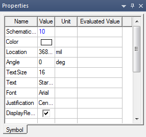
The contents of the Symbol tab vary depending upon the number and type of components, properties, and drawing elements selected in the schematic.
Symbol tab fields can be edited using the following guidelines:
Component Symbol
- Component Location – Click a cell in the Value column and enter a new set of X,Y coordinates for the symbol. Click a cell in the Unit column to assign a unit of measure to the coordinates. Press Return to move the component to the new location.
- Component Angle – Click a cell in the Value column and select an angle from the drop-down menu. The available choices are 0, 90, 180, and 270 degrees. The symbol rotates counterclockwise as soon as you select an angle.
- Component Mirror – Select a check box in the Value column to flip the component left-to-right. The mirror operation is performed as soon as you select the box. Clear the check box to return the symbol to its original orientation.
- Use Symbol Color – Select a check box in the Value column to use the default symbol color for the component. This hides the Component Color field and overrides the color set in it.
- Component Color — Click the colored bar in the Value field to open a palette from which to select a new color for the symbol. The new color is applied when the symbol is unselected.
Displayed Component Properties (Text)
- PropDisplay Location — Click a cell in the Value column to enter a new set of X,Y coordinates for the property. Click a cell in the Unit column to assign a unit of measure to the coordinates. Press Return to move the displayed property to the new location.
- PropDisplay Angle — Click a cell in the Value column and enter an angle. The property rotates counterclockwise when you press Enter or select another element.
- PropDisplay Font — Click a cell in the Value column and select a font from the drop-down menu. The displayed property font changes as soon as you select the new font.
- PropDisplay Font — Click a cell in the Value column and enter a font size. Font sizes are in points.
- PropDisplay Justification — Click a cell in the Value column and select a justification setting from the drop-down menu. The displayed property justification (position relative to PropDisplay Location) changes as soon as you select the new setting.
Primitive Drawing Elements
- Select a primitive drawing element in the schematic editor to view and edit its properties. Primitive drawing elements are arcs, circles, lines, rectangles, polygons, text boxes, and images. Editable properties vary with the kind of element. See Adding Primitive Drawing Elements for additional information on specific property types for each element.