
Symbol Graphic Object Levels
There are two display styles available for symbols shown in the schematic editor: IEEE and Traditional. The display style is set on the Schematic Editor Options > General tab. Each style contains two or more active levels for the graphic objects that comprise a symbol. Each graphic object in a symbol is associated with a level.
Graphic object levels are managed in the Symbol Editor by selecting View > Levels, which opens the Levels dialog box for the symbol currently being edited.
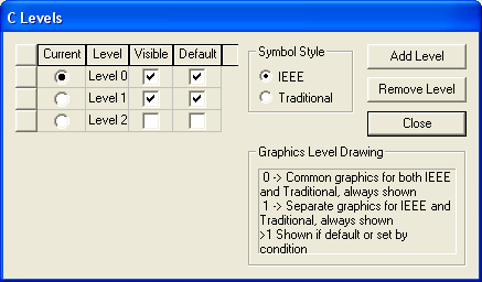
Levels may be shown or not depending on external settings.
- Level 0 graphics are common to both IEEE and Traditional symbol styles, and are always shown.
- All symbol pins are on level 0, and thus are common to both styles.
- Objects placed on level 1 in the IEEE style are always shown on the schematic when you choose the IEEE display style. Similarly, objects placed on level 1 in the traditional style are always shown on the schematic when you choose the traditional style option.
- Levels greater than 1 are independent for each style. Click Add Level to add any number of levels, for IEEE, Traditional, or both styles. Visibility of graphics on additional levels may be controlled with the Default check box in the Levels dialog box, in a special component dialog box, or programmatically. In Twin Builder, you can control visibility by setting up Boolean conditions using quantities, then evaluating the conditions as a simulation progresses.
To set the level and style of a graphic object:
- Choose the Level by selecting the radio button next to the desired level.
- Select IEEE or Traditional to choose the desired Symbol Style.
- Select and place the desired graphic object (circle, line, pin, text, and so on) from the Symbol Draw menu.
- When finished, Close the symbol Levels dialog box.