
Pin
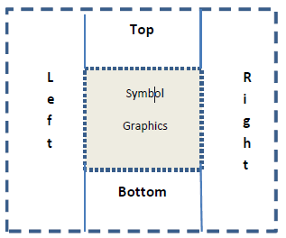
This option, also available from the Symbol Draw toolbar, initiates placement of a symbol pin with a default stem length of 100 mil. Press R to rotate a pin in 90 degree increments before placing it. Click the editor grid to finish placing the pin. Pins are always placed on the “0” level and snapped to the grid. After placement, press Ctrl-R to rotate the pin in 90 degree increments. You can also move and reorient pins as described below.
Adjusting Pin Orientation
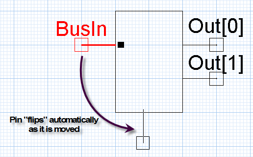
- If the Adjust Pin
Orientation on Drag option in the Schematic Editor Options: Symbol Editor Options Tab
is enabled, you can drag pins from one side of a symbol to another using
the mouse,
and the pins rotate or flip to the appropriate orientation.
- Ctrl+click
to select and drag multiple pins from one side of a symbol to another.
Note:
If multiple selected items include symbol graphics in addition to pins, then automatic pin orientation is disabled.
- Press the Alt key while dragging the pins to temporarily disable the automatic pin orientation function if Adjust Pin Orientation on Drag is enabled. Conversely, if Adjust Pin Orientation on Drag is disabled, pressing the Alt key while dragging the pin temporarily enables automatic pin orientation.
Other properties of the pin include its name, color, level, type, length, visibility of the pin name and number, and the circuit node to which the pin will be connected when hidden. See Editing Pin Properties for detailed explanations of these properties.
To edit these properties:
- Do one of the following:
- Click the pin and view its properties in the Properties pane.
- Double-click the pin and view its properties in the Properties dialog box.
- Right-click the pin and select Properties to view its properties in the Properties dialog box.
- Click the Value cell for the property you want to modify.
- Modify the value.
- Click OK, or click in another Value
cell to commit the change and keep editing values.
Note:
If you make a pin name or number visible, the text can be selected, moved, rotated, and modified like any other text label. However, a pin’s name and number remain linked to the associated pin.