
Overview of FMU Coupling with Twin Builder
The following overview describes the procedure for adding an FMU component in a Twin Builder design. Twin Builder supports import of model exchange and co-simulation. It supports both FMI standard 1.0 and 2.0.
- Obtain or create an FMU using the FMI
standard.
Note:
See the FMI web site (https://www.fmi-standard.org/) for detailed information on creating an FMU model.
-
Select Twin Builder > Add Component > Add FMU Component and use the Select FMU Model File dialog box to locate and open the FMU model .fmu file to add to your schematic.
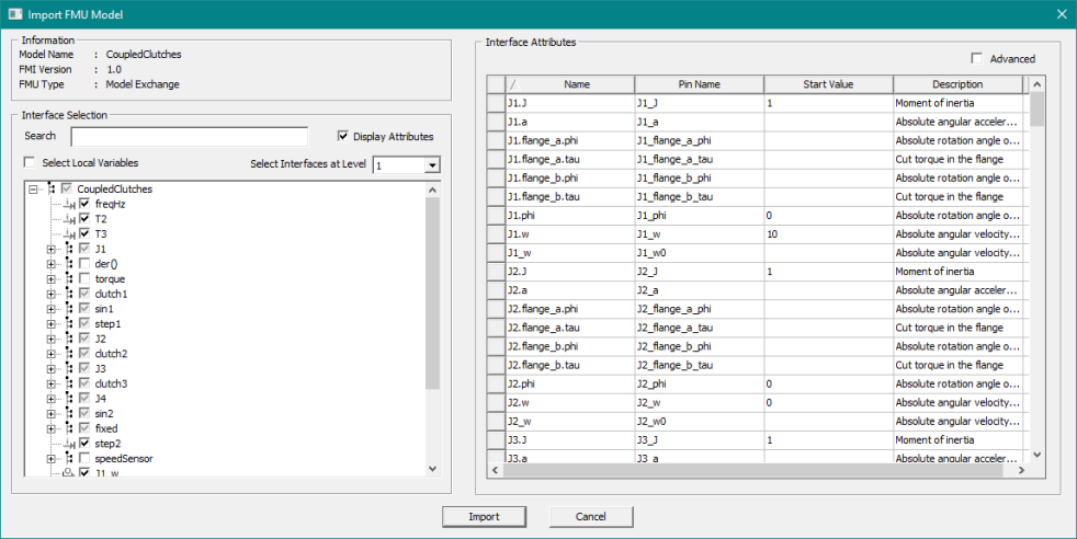
When you select an FMU file, the Import FMU Model dialog box lets you choose interfaces to expose in the Twin Builder component.
- Select Local Variables – Include internal or local output properties in the model. Leave it cleared to exclude these properties from selection.
- Select Interfaces at Level – Choose the desired hierarchy level from the drop-down list. The value you choose selects input and output interfaces up to the chosen hierarchy level for inclusion in the model.
An FMU often has thousands of interfaces. For better performance, select only necessary inputs and outputs. Use Edit Model to add/remove interfaces in the model.
- Interface names that start with “_” are grouped under AdvancedSettings.
- Interface names that indicate derivative (der(<name>)) are grouped under der().
FMU Version 1.0 for Model Exchange
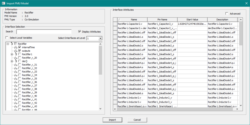
FMU Version 2.0 for Co-Simulation
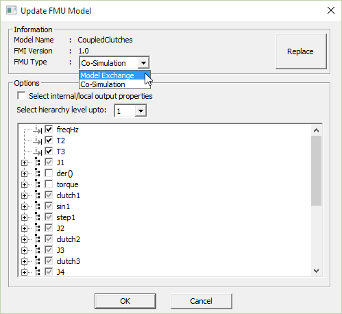
The following figure shows the drop-down list provided when an FMU supports both Model Exchange and Co-Simulation. Use the drop-down list to change the type of FMU.
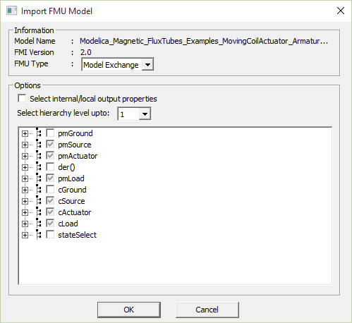
When you import an FMU and are shown a choice to select Model Exchange/Co-Simulation, if you select an option that is not supported by the imported FMU, the simulation terminates with the following error: Unable to load DLL for FMU_Link_.
Twin Builder doesn’t support periods (.) or brackets ([ ]) characters in interface or property names; they will be replaced by an underscore (_).
For example,
assembly.subassembly.part.lengthbecomesassembly_subassembly_part_length-
assembly.part[0].lengthbecomesassembly_part_0_length
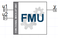
After you click OK, Twin Builder brings the FMU into the project file and creates a component ready to place on the schematic. If the FMU model contains a model symbol .png file, it is used as the component symbol. Otherwise, Twin Builder uses the default symbol shown below.

- Place the component on the schematic.
Double-click the FMU component to open its Properties dialog box, in which you can view and edit the various quantities and parameters.
- Create the rest of the simulation design on the schematic.
- Simulate in Twin Builder and analyze results.
Initialization of Input Values
Initial values of inputs can be specified using two ways:
- Input pin values at time=0 by setting UseStartValueInitialization to “false”.
- Corresponding _start parameters by setting UseStartValueInitialization to “true”.
The first option is appropriate if the source of the input is from constant blocks, FML_INIT block, timer function components, and so on. However, if the input is connected to a quantity that depends on other components, it could lead to initialization failure due to improper initial values. Specifying the initial conditions for the inputs (the second option) is always the preferred way to initialize the model. The start parameters have the same name of the input plus _start suffix.
TS_TwinBuilder: Sample Time Parameter for FMI Co-Simulation
For Co-Simulation FMUs, Twin Builder has an additional parameter called TS_TwinBuilder. If this value is not specified, the FMU is evaluated at the same (variable) time step as the circuit simulator. When it is specified, Twin Builder evaluates this FMU only at every sample point.
Ansys recommends that you do not rely on sample time for a Co-Simulation FMU that only supports fixed step-size. There is no absolute guarantee that all the sample points will be hit exactly at the required intervals when the Twin Builder solver takes a variable time stepping. Therefore, in order to guarantee a successful simulation, we highly recommend that you set a fixed step scheme as follows:
HMIN = HMAX = Required fixed step-size of the FMU
Replacing an FMU with an FMU of a Different Standard
You can replace a model from FMI 1.0 with FMI 2.0, and vice versa.
- Right-click the FMU in the schematic and select Edit Model.
- In the Update FMU Model dialog box, click Replace and select the new model. The dialog box shows the new FMI version.
- Click OK to update with the new model.
The FMU component definition and all instances of this component are updated. The FMU component uses the new FMU file.
Replacing an FMU with a Different FMU Type
You can replace an FMU with a different FMU type.
- Right-click the FMU in the schematic and select Edit Model.
- In the Update FMU Model dialog box, click Replace and select the new model. The dialog box shows the FMI version and FMU type. You can change the type by using the FMU Type drop-down list.
- Click OK to update with the new model.
The FMU component definition and all instances of this component are updated. The FMU component uses the new FMU file.
Replacing an FMU with an FMU that has Different Outputs
You can replace an FMU with an FMU that has different outputs.
- Right-click the FMU in the schematic and select Edit Model.
- In the Update FMU Model dialog box, click Replace and select the new model. The dialog box shows the new FMI version.
- Click OK to update with the new model.
The FMU component definition and all instances of this component are updated. The FMU component uses the new FMU file.
Replacing an FMU with an FMU that has Different Identifiers
Follow this procedure to replace an FMU with an FMU that has different Identifiers.
- Right-click the FMU in the schematic and select Edit Model.
- In the Update FMU Model dialog box, click Replace and select the new model. The dialog box shows a message that the new FMU model identifier doesn't match with the current one and asks if you want to continue with the update.
- Click Yes to update the component.
- Click OK
The FMU component definition and all instances of this component are updated. The FMU component uses the new FMU file.
Storage of large FMU files (>100MB)
Normally, FMU model files that get imported are included in the project file. With large FMU files (>100MB), this can lead to a significant slowdown of saving and loading the project file. In order to prevent a negative impact, large FMU files are stored on disk in a special project data folder (for example, <projectdir>\project1.aedtdata). Since those files are part of the project, this folder needs to stay with the project file. We recommend that you use the file commands available in Ansys Electronics Desktop (Save As, Rename, Archive, Restore Archive) in order to perform project operations that would change the location or name of the project file. If those operations are done manually using an external file explorer, you must include and adjust the data file folder and its content. Also, in that case the proper functioning of the FMU components is not guaranteed. In most cases, if an external FMU data file got lost, you can recompile it if the model text is available. You can also click Update Model on the FMU component to import the FMU file again.
Interface Grid
Select the Display Attributes check box to open the interface grid, which displays the variables' attributes. Use the Advanced check box to toggle the number of rows displayed.
Selecting a variable in the interface tree will highlight the corresponding attributes in the interface grid.
Variable Search
To search for a variable in the tree, enter a variable name in the Search box. The tree display updates, showing all variables matching your search text.
Remove Unused Definitions cannot be undone. If unused FMU models are removed, their external data files will also be removed from the disk. If the project is not saved with the same name before closing, any external FMU data file that was connected to the original project and was removed during Remove Unused Definitions cannot be retrieved. In order to save a cleaned-up version of a project under a new name, first save the project under the new name, remove the unused definitions, then save the new project again.