Output Configurations
During the simulation a large amount of data will be produced. These data can be displayed directly on the screen or saved in files through output specifications.
- Online Graphic Output
To display the simulation results during the simulation, specify a View Display (VIEW) as the output destination.
- Output in Files
To evaluate data with other tools, specify the Twin Builder database (SDB) as the output destination. For all output channels, the simulator creates an SDB file. The file name is formed from the name of the SML file and the extension SDB.
Every output destination can be assigned any system quantities from the electrical circuit, the block diagram, the state graph and formulas, functions and variables. It is also possible to define a system quantity for several output destinations.
|
|
||
|
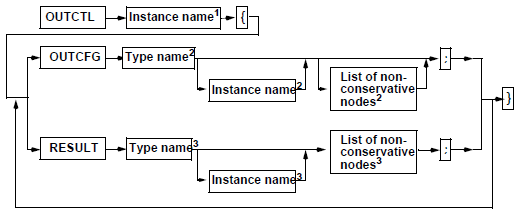
Instance name 1 |
Name of the output control instance. |
|
|
Type name 2 |
Name of the used output device = { VIEWTOOL | SimplorerDB }. |
|
|
Instance name 2 |
Instance of the used output device. |
|
|
Nonconservative nodes 2 |
List of nonconservative nodes (parameters of the output device) separated by a comma. |
|
|
Type name 3 |
Name of the used result format= { VIEW | SDB }. |
|
|
Instance name 3 |
Instance of the used result format. |
|
|
Nonconservative nodes 3 |
List of nonconservative nodes (output quantities) separated by a comma. |
|
|
//Output Configuration OUTCTL OutCtl1{ OUTCFG VIEWTOOL Out1 ( Xmin := 0, Xmax := Tend, Ymin := -400, Ymax := 400 ); RESULT SDB SDB_0( E1.EMF ); RESULT SDB SDB_1( STEP1.VAL ); RESULT VIEW VANALOG_2 ( E1.EMF, Type:=ANALOG ); RESULT VIEW VANALOG_3 ( C1.I, Type:=ANALOG ); OUTCFG SimplorerDB DB1 ( Xmin := 0, Xmax := Tend, Reduce := 0, StepNo := 2, StepWidth := 10u ); } |
||