
Drawing Bus Entry Objects
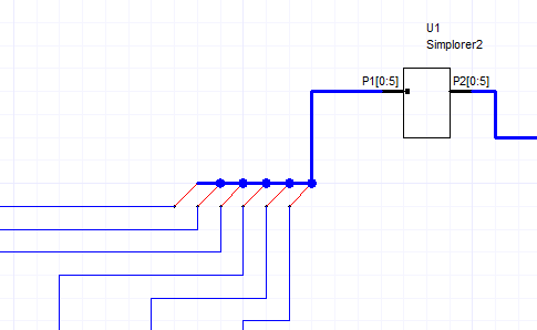
Select Draw > Bus Entryto add visual representations of connections from a bus to an individual net or a sub-bus. On a schematic, a bus may be shown with individual nets (wire) or with wires where the bus width is greater than 1 (drawn with a thick blue line). The Bus Entry object provides a mechanism for visually representing individual wires connected to a bus consisting of multiple nets as shown in the following example. In this example, the P1[0:5] bus is visually “connected” to individual wires via the bus entry objects (the diagonal red lines).
- Bus Entry objects provide only a visual representation of connections on the schematic - not actual connections. You still must ensure that connectivity is maintained by properly naming the wire segments drawn out of a bus.
- Because they are merely visual representations of connections, Bus Entry objects have no significance or effect on the actual circuit, and thus do not appear in the net list or in any results.
- Bus Entry objects are used to show connections to nets of any width and any domain.
- Both ends are only attached to nets and cannot be directly attached to other pins or ports.
To add bus entry objects to an existing schematic containing a bus:
- Add a bus to the schematic by drawing a wire and naming it as a bus. For example: DataBus[0:2].
- Place a Bus Entry from the Draw menu such that one end intersects the bus.
- Draw another wire from the other end of the Bus Entry object.
- Rename this new wire as DataBus[0] to use that element of the bus as the individual net.
- Repeat as needed for the remaining bus elements.
Disconnects
A disconnect is a circular visual indicator at the pin of a bus entry object. Its presence indicates that two nets – though visually connected through the bus entry object – are actually disconnected as indicated by the differing names.
If a bus entry has both pins connected to two different nets (which can be of different sizes) and if neither of the named nets are a subset of the other named net, a disconnect circle will be drawn.
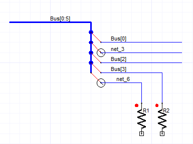
The figure above shows a bus named Bus[0:5], which has five nets that are branched out through bus entry objects. Three nets are named properly as: Bus[0], Bus[2] and Bus [3]. However two nets: net_3 and net_6 are not connected to the bus by name - and thus are shown drawn with circular disconnect objects.