Connecting Components
Connect components on a sheet using wire mode, or by dragging one pin of a component over another pin of the same type.
By default unconnected component pins (terminals) will generate errors (displayed in the Message Manager pane) when a netlist is generated. Simulation is not possible until the errors are corrected.
You can change this default component behavior Using the Component Editor so that either “No Action” is taken when unconnected terminals are netlisted; or that unconnected terminals are “Grounded”.
Direct connections between interface ports, or between an interface port and ground, are not allowed
Connections (wires) for the various domains are distinguished by default colors. For example, green for hydraulic, orange for magnetic, black for electrical, and so on. Connections between different domains are blue. These default colors can be set on the Colors tab in the Schematic Editor Options dialog box.
To start drawing a wire, do one of the following:
- On the desktop’s Draw menu, click Wire.
- Press Ctrl+W.
- Click the desktop’s Wire icon
 .
.
- Move the mouse cursor over a component pin to display the X-shaped wiring cursor:
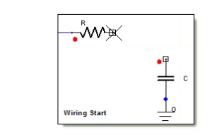
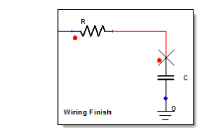
To draw connections:
- Click at the point where you want the wire to start, and move the cursor to extend the wire. As you move the cursor, click wherever you want to turn a corner.
To stop drawing a wire, do one of the following:
- Click, if the wire ends at a port or component pin.
- Double-click, if the wire does not end at a port or component pin.
- Press the spacebar to terminate the wire operation and leave the net unselected.
- Press Enter to terminate the wire operation and leave the net selected.
- Right-click and select Place and Finish.