
Adding an HFSS Solution Setup
There are two ways to add an HFSS solution setup:
In addition its own settings, SI Xplorer respects any HPC and Analysis Options selected for the HFSS 3D Layout design type in Ansys Electronics Desktop.
HFSS Auto Setup
To add an HFSS Auto solution setup:
- Click Simulation > Add HFSS Solution Setup > Auto.
Auto setup features a simplified window with a slider bar that you can adjust from Higher Speed (which sacrifices accuracy to achieve optimum speed) to Balanced (which is more accurate but faster than the highest accuracy setting) to Higher Accuracy (which takes the time to ensure optimal accuracy).

The auto setup includes a single sweep, for which you can edit the Distribution, Start, and End. The design must include one or more ports.
Use the Sweep Type drop-down menu to select either:
- Discrete – generates field solutions at specific frequency points in a frequency range.
- Interpolating – estimates a solution for an entire frequency range using an adaptive rational function interpolation method. Using an Interpolating Fast sweep will result in faster analysis, however the current distribution values cannot be saved.
When Use Q3D to solve DC point is selected, the HFSS solver invokes Q3D Extractor to explicitly solve for a DC point. The mesh from HFSS is used for the Q3D extraction, with sources and sinks defined based on HFSS port assignment. Matrix reductions are automated to integrate the Q3D results with HFSS.
Use the Frequency Sweeps area to specify sweeps in terms of Distribution type, which can be:
- Linear Step
- Linear Count
- Log Scale
- Single Point
- Single Point Sweep, which adds a set of 10 Single Point Sweeps defaulting from 1 GHz to 10 GHz in increments.
To add more sweeps (including mixed sweep types), use the Add Above and Add Below buttons. This feature provides flexibility (e.g., you can define sweeps with log scale at lower frequencies and linear step at higher frequencies).
If appropriate, use the Defaults tab to save your settings as the default or revert to the original settings.
HFSS Advanced Setup
To add an HFSS Advanced solution setup:
- Click Simulation > Add HFSS Solution Setup > Advanced.
The settings for Advanced setup are divided into eight tabs:
- General – general solution settings.
- Options – settings for lambda refinement, adaptive analysis and solution, order of basis, and whether to enable the use of solver domains.
- Advanced – settings for defeaturing a mesh, which model type to use, and vias.
- Advanced Meshing – settings for curve approximations and layer alignment.
- Solver – port settings and configurations for modeling.
- DC R – settings for the DC Resistance and Inductance analysis.
- Defaults – enables you to save the current settings as the defaults for future solution setups or revert the current settings to HFSS's standard settings.
HFSS Advanced Setup – General Tab

The General tab allows you to set the following:
- Setup Name – Name of the setup. It must be unique.
- Enabled – If not enabled, this setup cannot be analyzed and will be not included in a general “Analyze” of all setups.
- Solution Frequency – Specify the frequency
and units at which to generate the solution. If a frequency sweep is
solved, an adaptive analysis is performed only at the solution frequency. The following fields change according to your selection:
- Frequency – The adaptive frequency for refinement.
- Low Frequency – The smallest adaptive frequency for refinement for a Broadband.
- High Frequency – The largest adaptive frequency for refinement for a Broadband.
- Maximum Number of Passes – The maximum number of mesh refinement cycles that you would like HFSS to perform. This value is a stopping criterion for the adaptive solution. If the maximum number of passes has been completed, the adaptive analysis stops. If the maximum number of passes has not been completed, the adaptive analysis continues until the convergence criteria are reached.
- Maximum Delta S – The magnitude of the change of the S-parameters between two consecutive adaptive passes. This is a stopping criterion for the adaptive solution. If the magnitude of the change of all S-parameters are less than this value from one iteration to the next, the adaptive analysis stops. Otherwise, it continues until the requested number of passes is completed.
- Output Var. – A button labeled Add
to add output variables to the refinement criteria for that frequency
or Edit to edit the output variables for that refinement
criteria. Selecting this option brings up the Advanced Mesh Convergence
dialog box or displays the error message 'You must have at least one
output variable defined' if you have no output variables defined in your
design. Users may receive the error 'You must have at least one output
variable defined that returns a single real value (as opposed to complex,
etc)'.
- Output Variable – The name of the output variable.
- Include – A check box for whether to include the value of this output variable in the mesh convergence calculations.
- Max Delta – The maximum amount of change appropriate in the output variable between adaptive passes. It is a stopping criterion for the adaptive solution. If the output variable changes from one iteration to the next by an amount that is less than Max Delta, the adaptive solution.
- Add – Adds a new frequency to the table.
- Remove – Removes a selected frequency from the table.
- Fields – Click Save fields to post process or plot fields. This is only available for Discrete Sweep Types. To restrict the fields saved to radiated fields, click Save radiated fields only.
- Use Defaults – The target defaults depend on the Order of Basis function selections (e.g., for Driven solutions and a First Order basis function, the default target is 0.3333. HFSS refines the mesh until most element lengths are approximately one-third wavelength).
HFSS Advanced Setup – Options Tab

The Options tab allows you to set the following:
- Initial Mesh Options:
- Do Lambda Refinement – Lambda refinement is the process of refining the initial mesh based on the material-dependent wavelength.
- Lambda Target – The fraction of the wavelength that determines the refined tetrahedra edge length (e.g., if the value is 0.1 then a edge length of 0.1 is used as the refinement target).
- Use Defaults – The target defaults depend on the Order of Basis function selections (e.g., for Driven solutions and a First Order basis function, the default target is 0.3333; HFSS refines the mesh until most element lengths are approximately one-third wavelength.).
- Adaptive Options:
- Maximum Refinement Per Pass – determines how many tetrahedra are added at each iteration of the adaptive refinement process. The tetrahedra with the highest error is refined. The value is a percentage.
- Maximum Refinement – The maximum number of tetrahedra that can be added during an adaptive pass. By default, this unchecked, to that there is no maximum. If you enable the Maximum Refinement, the initial value is 1000000.
- Minimum Number of Passes – The maximum number of mesh refinement cycles that you would like HFSS to perform. This value is a stopping criterion for the adaptive solution. If the maximum number of passes has been completed, the adaptive analysis stops. If the maximum number of passes has not been completed, the adaptive analysis continues unless the convergence criteria are reached.
- Minimum Converged Passes – An adaptive analysis does not stop unless the minimum number of converged passes has been completed. The convergence criteria must be met for at least this number of passes before the adaptive analysis stops.
- Solution Options:
- Order of Basis Functions – The order of the basis functions HFSS uses to interpolate field values from nodal values. The Zero order option is useful when a model requires a mesh that produces more than 100,000 tetrahedra, but the model size is small compared to wavelength. The higher order options solve progressively more unknowns for each tetrahedra. Mixed order uses higher order where more accuracy is required, and lower order where fields are weaker.
- Enable Iterative Solver – The iterative solver provides an alternative to the multi-frontal solver when a matrix is well-conditioned for an iterative solution. The iterative solver significantly reduces memory usage, and it can also provide a savings in the solution time for large simulations. When this option is enabled, HFSS automatically invokes the iterative solver when it decides that the matrix is conditioned well enough to take advantage of the iterative approach. HFSS uses the multi-frontal solver if the matrix does not meet this requirement.
- Relative Residual – The residual measures the convergence of the iterative solver. The default value is 1E-4.
- Enhanced low frequency accuracy – When enabled, the solver is tuned to reliably solve low frequencies for designs that only contain lumped ports as sources or a combination of lumped and circuit ports. In addition, for designs with only lumped ports and/or circuit ports, interpolating sweeps are tuned to solve more low frequency points in order to accurately represent very low frequency results.Note:
This requires more RAM in order to solve the entire solution vector for interpolation sweeps and for discrete sweeps not saving fields.
HFSS Advanced Setup – Advanced Tab

Use the Advanced tab to set the following:
- Defeaturing Options:
- Form polygon unions before meshing – specifies whether all objects are combined or “unioned” before meshing takes place. This can simplify the mesh; it can, however, also remove internal boundaries that may be desirable. “Unioning” is a complex operation and sensitive to almost coincident edges; in some instances, a union may produce undesirable results. Inspecting the mesh is a simple way to verify the operation.
- Remove voids with an area smaller than <value> – simplifies meshing by removing small voids.
- Remove Floating/Inactive Signal Net Geometry – approximates a mesh by removing inactive geometry.
- Model Type Options:
- General – this model offers standard mesh processing.
- Use polygon defeaturing – removes very close
points, points that do not contribute to the geometry of an edge (e.g., collinear), and very thin intrusions. When used with "unioning", it can
be helpful in healing geometry that is not snapped together.
- Tolerance as a ratio of the data exent – tolerance value specified as a ratio of the overall data extent. This value must be very small.
- Absolute distance – tolerance specified as an absolute value (e.g., 0.0001mm).
- Point -to-edge and point-to-point snapping – snaps points to edges and points to points if they are within a minimum dimensional tolerance. This tolerance is based on geometry extents.
Note:From the Vias area, vias may be modeled as a simple 'wirebond' or as a 3D ribbon or solid. The values specified in the analysis setup only apply to vias that do not have specific property overrides; all properties explicitly specified for a via take precedence over these values.
- Use polygon defeaturing – removes very close
points, points that do not contribute to the geometry of an edge (e.g., collinear), and very thin intrusions. When used with "unioning", it can
be helpful in healing geometry that is not snapped together.
- IC [Beta] – this model type optimizes mesh processing to simulate on-chip structures.
- General – this model offers standard mesh processing.
- Vias Options:
- Mesh as a 3D via – vias are modeled using rectangles to form a 3D ribbon or solid.
- Number of sides – number of sides to use when creating the 3D representation. If less than 3, the via is modeled as a flat ribbon.
- Via Field – this option is disabled in SI Xplorer.
- Via material default – when a material has not been specified in the padstack definition and there is no override in the properties for a via, then this is the material associated with the via mesh. It is initially set to copper.
- Mesh as a 3D via – vias are modeled using rectangles to form a 3D ribbon or solid.
HFSS Advanced Setup – Advanced Meshing Tab

Use the Advanced Meshing tab to set the following:
- Circle and arc approximation – circles and arcs
must be replaced with straight edge approximations before meshing. There
is no attempt to match areas. Points are simply introduced on the original
arc at the locations specified by the following parameters.
- Arc setup size – the angular interval below which mesh points are added.
- Starting azimuth for circles – specifies the location of the first mesh point or circles.
- Maximum number of arc points – the maximum number of mesh points on a given arc segment.
- Use arc to chord error approximation technique for arc – the resulting straight edge approximation will not deviate from the original arc by more than the specified error.
- Maximum arc to chord error – maximum distance permissible between a straight edge approximation (the chord) and the original arc.
- Hierarchical Layer Alignment – aligns layers across hierarchical boundaries.
- Snap tolerance – When layers across hierarchical boundaries are within this unitless tolerance, they are aligned to the same elevation. This value represents a fraction of total stackup height.
HFSS Advanced Setup – Solver Tab

Use the Solver tab to set the following:
- Port Options:
- Maximum Delta Zo – specify Zo as a target percentage. The default is 2%.
- Set Triangles for Wave Port – controls the number of triangles used for a wave port. For designs with lumped ports, this option is not active. Higher numbers of triangles would not benefit a solution setup in this case. Set values for the Min and Max number of triangles.
- Modeling Options:
- Signal layers thinner than <value> are modeled as zero thickness – Negative signal layers in the design which are thinner than the given value are modeled as being infinitely thin in order to reduce simulation time.
- Dielectrics thinner than <value> are merged with an adjacent – Dielectric layers in the design which are thinner than the given value are merged into an adjacent dielectric. Material properties are accumulated using a weighted average.
- Enable intra-plane coupling of Pwr/Gnd nets for enhanced accuracy
HFSS Advanced Setup – DC R Tab

Use the DC R tab to set the following:
- Maximum Number of Passes
- Minimum Number of Passes
- Minimum Converged Passes
- Percent Error
- Percent Refinement Per Pass
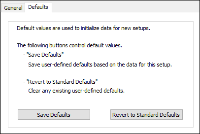
HFSS Advanced Setup – Defaults Tab

Use the Defaults tab to save your settings as the default or revert to the original settings.