
AC Resistance Matrices
The resistance matrix gives the relationship between voltage drops and currents.
For example, the transmission structure below consists of two regular conductors, one of which has multiple sources of current.
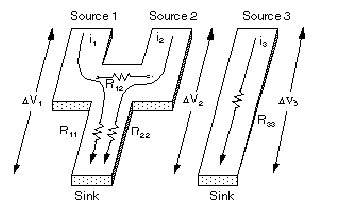
The voltage drops are given by:
DV1 = i1R11 + i2R12+i3R13
DV2 = i2R22 + i1R12+i3R13
DV3 = i3R33 +i1R13+i2R23
where:
R11, R22, and R33 are the self-resistances of each current path.
R12is the mutual resistance between current paths 1 and 2. Mutual resistance only applies to current paths within the same net (that is, conductor nets that have multiple sources of current).where:
R13 is the mutual resistance between paths 1 and 3. R23 is the mutual resistance between paths 2 and 3.
Mutual AC resistance between regular conductors on distinct nets is non-zero.
At non-zero frequency, two phenomena begin to affect the resistance matrix:
- Current within a conductor begins to accumulate near the periphery (skin effect). This reduces the effective cross-section through which the current travels, thus increasing the resistance.
- Current in one net induces currents in adjacent nets. Induced currents cause additional power loss, thus increased self-resistance. These induced currents create a non-zero mutual resistance between conductors.
AC resistance is computed after determining the surface currents on a net. Surface currents are computed as a step in determining AC inductance.