
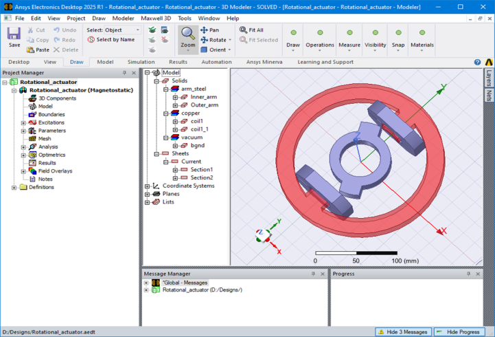
The Maxwell Desktop
The following graphic shows the different sections of the Maxwell desktop:
General Procedure for Setting Up Maxwell Designs
You are not required to follow a specific order when setting up your Maxwell design. However, the following order is recommended, particularly for new users:
- Open Ansys Electronics Desktop by double-clicking the desktop icon or by clicking Start > Programs > Ansys EM Suite [version] > Ansys Electronics Desktop [version] from the Windows taskbar.
- Add a Maxwell 3D design and save the new project.
- Draw the geometry of the model.
- Optionally, modify the model's design parameters.
- Assign variables to design parameters.
- Assign excitations and boundary conditions.
- Specify solution settings.
- Run a Maxwell simulation.
- Create postprocessing plots.
- Create a parametric analysis.
- Create a field animation of the parametric analysis results.
About the Example Design
The application described in this Getting Started guide is an extension of the TEAM Workshop Problem 24 rotational actuator design. The geometry is shown below:
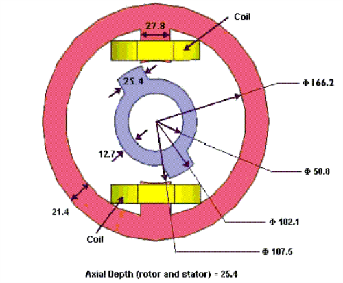
The outer part is a ferromagnetic nonlinear armature carrying two coils. The inner part is made of the same nonlinear material and can rotate around an axis. The inner and outer parts of the device are coaxial.
The field distribution will likely cause the flux density to concentrate in the two steel armatures in the regions where the distance between them is minimal. The expected edge effect will then further increase the field concentration.
In this example, we will compute the torque acting on the inner armature and the flux linkage of the two coils. For a presentation of the results and the corresponding FEM code, see the IEEE Transactions on Magnetics, Vol 38, No. 2, March 2002, pp 609-612.