
Context Area
The panel at the upper right of the window identifies
the context to be used for the calculations. The top line identifies
the design.
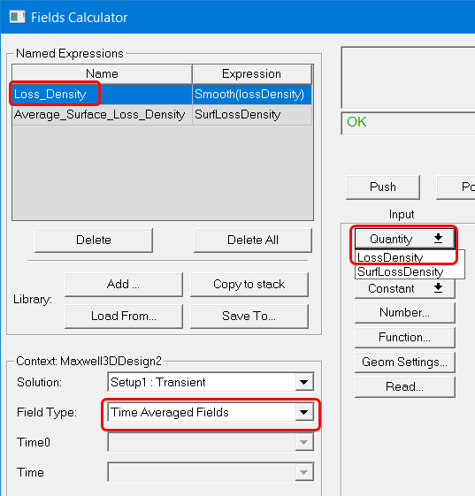
For Maxwell 2D and 3D transient solutions, the field type can be either Fields or Time Averaged Fields. Selecting Time Averaged Fields adds an additional Time0 field, which is used when calculating time averaged losses. Selecting Time Averaged Fields also adds Loss_Density as a Named Expression, and LossDensity as a Quantity command selection.
When coupling a Maxwell transient solution with an Icepak design, the field type must be Time Averaged Fields. Selecting Time Averaged Fields adds an additional Time0 field, which is used when calculating time averaged losses. Selecting Time Averaged Fields also adds Loss_Density as a Named Expression, and LossDensity as a Quantity command selection.
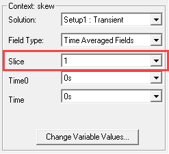
For Maxwell 2D transient solutions in which Use Skew Model is enabled on the Model Settings tab, an additional Slice field displays, which allows you to select the skew model slice to use for fields calculations.
The Field Type here is not related to the edit sources. This is a general term among Ansys EM products (HFSS, Maxwell, Q3D, Icepak, and Mechanical). Some products have more than one field type for different solution types. If only one Field Type is available the drop-down menu is unavailable.
The Change Variable Values button opens a Set Variable Values dialog box. By default, it has Use Nominal Design checked. Unchecking the box lets you select another variable value. OK the dialog box to accept the selection.