TAU2D: Band Mapping Angle Mesh (Clone+Symmetry)
Band Mapping Angle is a new meshing option for transient simulation of motors in Maxwell 2D. When selected, the meshing process will ensure that each mesh segment on the outside of the band (the curve that separates the static and moving regions) has exactly the sweep angle that has been specified by the user. For example, for a quarter model with 90 degrees of matching boundaries, specifying a band mapping angle of 0.5 degree will result in a band outline having 180 mesh segments of equal length.
Because the meshing angle is determined by this setting, the band object must have a curved outline, using zero segments.
To use the 2D Band Mapping Angle function:
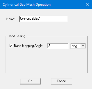
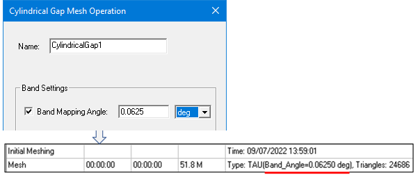
- When you open a 2D transient project, select Maxwell 2D > Mesh > Assign Mesh Operation > Cylindrical Gap Treatment, which opens the Cylindrical Gap Mesh Operation dialog box.
-
Select Band Mapping Angle, set the desired mapping angle, then click OK.
Note that it is best to synchronize the transient simulation timestep with the band mapping angle. For example, suppose the following mapping angle is used to accurately model the cogging torque:
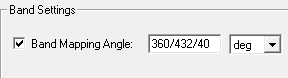
If the motor’s rotational velocity is 1 degree/second, then the following timestep should be used:
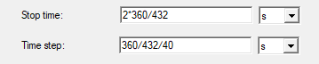
This practice will help to remove numerical noise in the results.
There are two ways to verify that the band mapping angle has been applied to a simulation:
- The specified angle will appear under Initial Meshing, on the Mesh line after “TAU”:
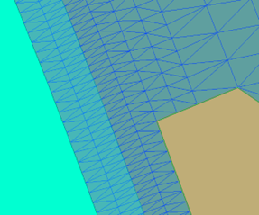
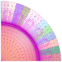
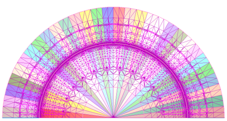
- The effects of the mapping angle will be seen in mesh plots:
- An additional layer will be created on both sides of the band.
- The triangle orientation will be exactly the same on each side of band, to eliminate noise.
- The layered structure will extend to the moving and static regions.
- Mesh density will smoothly transition from fine to coarse with distance from the band.
- Clone mesh if the region is repeatable.
- Mirror mesh if the region is symmetrical.
- Sweep layer mesh if the region is not repeatable.
Notes
- This feature is intended to replace the use of wire bodies to guide meshing in the band. However, if wire bodies are included, the mesh will respect them along with the band mapping angle.
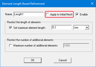
- Length-based mesh operations applied to an initial mesh (on objects, faces, or edges) are not yet supported. These mesh operations will be ignored by the mesher if a band mapping angle mesh is requested. However, these mesh operations can be used if Apply to Initial Mesh is not activated in the Element Length Based Refinement dialog box:
- Eccentricity is not supported.
- Segmented circular edge is not supported.
- This feature is limited to Maxwell 2D transient models with a Cylindrical Gap mesh operation.
- The Band Mapping Angle mesh operation does not currently support models with translational motion.
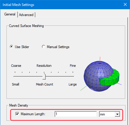
In addition, the global Maximum Length setting in the Initial Mesh Setting window can be used in conjunction with the Band Mapping Angle function to control mesh size.