Create Conduction Design
Create Conduction Design allows you to generate a conduction-only copy of your design. The toolkit creates a wall boundary condition with Heat Transfer Coefficient enabled for the external condition. The wall boundary condition is applied to the external faces using automatic or manual face selection.
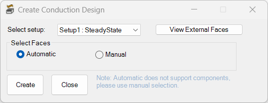
| Select setup | From the Select setup drop-down, select the solve setup to use in generating the results for the sub-model. |
| Select Faces | Under Select Faces, select Automatic to automatically select external faces of all supported geometries See Supported and Unsupported Geometry for more information. Select Manual to manually select a fewer number of external faces in the model. |
| View External Faces | Click View External Faces to display a list of all external faces in the model. See External Faces for more information. If Automatic is selected, the Info dialog box displays all faces that are automatically identified. If Manual is selected, the dialog box displays faces that you have manually selected. |
| Create | Click Create to generate the conduction-only design based on the selected faces. |
| Close | Click Close to close the toolkit without creating a conduction-only design. |
If you encounter an unhandled exception error when attempting to run the Create Conduction Design toolkit, set the following environment variable:
ANS_USE_ISOLATED_CLIPBOARD = 1
Supported and Unsupported Geometry
The Create Conduction Design toolkit supports many types of geometry but has some limitations:
- Supported: primitive objects, CAD, 3D components (Manual selection), PCB native component Bounding Box outline (Manual selection)
- Unsupported: hollow objects, subregions, and native 3D components (polyline PCBs, heatsinks, CTMs, and fans)
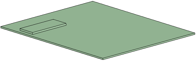
External Faces
External faces are sheet geometry that form the outer boundary of the model. In the following image, Box 1 is located on top of Box 2. In this example, automatic selection would identify five external faces for Box 1 since the bottom sheet coincides with the top of Box 2 and is not exposed.