
Displaying the Mesh
Once you have generated a mesh, you can examine it to determine if it meets your needs. Icepak provides tools for viewing the mesh on individual objects, as well as on cross-sectional planes that extend throughout the cabinet.
Scripting does not record steps performed in the Mesh visualization dialog box.
| Select | From the Select drop-down list, select the mesh to display in the 3D Modeler window. You can select the Design Mesh or another solution setup from the design. The design mesh is the mesh generated based on the current design's geometry and mesh settings. Other solution setups can contain imported mesh from linked designs. See Adding a Mesh Linked Solution Setup and Importing Mesh for more information. |
| Num elements | Num elements displays the number of mesh elements that exist in the global mesh region. Fine mesh settings result in higher element counts. |
| Selected object surface elements | When Geometry/Boundary selection is enabled, Selected object surface elements displays the number of surface mesh elements of the currently selected objects. |
| Mesh display on | |
|---|---|
| Show | Show displays the mesh. |
| Cut plane | Cut plane displays the mesh on a cross-sectional plane. |
| Geometry/Boundary selection | Geometry/Boundary selection displays the mesh on object geometry selected in the 3D Modeler window or history tree or a thermal boundary condition selected in the Project Manager. When selecting geometry in the 3D Modeler window, you can select and display mesh on objects or faces. |
| Plane Location | |
| X, Y, Z plane through center | X plane through center, Y plane through center, or Z plane through center specifies a plane cut through the center of the model that is aligned with the Cartesian axis. |
| Select a face/plane | Select a face/plane displays the mesh on a plane based on your selection of a geometry face or plane in the 3D Modeler window or history tree. |
| Point and normal | Point and normal specifies a point on the plane and the normal direction to the plane. Enter coordinates (PX, PY, and PZ) to specify the point. Enter a vector defining the direction normal to the plane (NX, NY, and NZ). For example, entering NX = 1, NY = 0, and NZ = 0 for the vector defines normal pointing in the x direction. |
| Coeffs (Ax + By + Cz = D) | Coeffs (Ax + By + Cz = D) specifies an equation that defines the plane. Enter the coefficients A, B, C, and D for the equation. |
| Horizontal - screen select | Horizontal - screen select displays a horizontal plane cut of the mesh at a selected point in the 3D Modeler window. |
| Vertical - screen select | Vertical - screen select displays a vertical plane cut of the mesh at a selected point in the 3D Modeler window. |
| Display Attributes | |
| Sectioned | Sectioned displays a two-dimensional cross-section of the mesh when viewing a plane cut. |
| Raw elements | Raw elements displays a three-dimensional plane cut of the mesh. When Surface only is selected, only the outer surface of the plane is displayed. |
| Surface only | Surface only displays only the surface mesh. |
| Full Mesh | Full Mesh displays the full mesh of selected geometry or boundary conditions, including areas overlapping with other geometry. See Reduced Mesh and Full Mesh. |
| Wire | Wire displays the generated surface mesh lines. |
| Shaded | Shaded displays the generated surface mesh filled with the color for the selection in the drop-down menu. |
| Grid | Grid displays wire mesh lines over the Shaded mesh display. |
| Color | Color defines the color in which the mesh is displayed. |
| Color by object | Color by object displays object mesh faces and/or cells using the object color defined in its Properties window. Otherwise, the mesh faces will be shown using the Color setting. |
| Plane transparency | Plane transparency controls the mesh plane transparency when Shaded is selected. Move the slider bar to display different levels of transparency. |
| Geometry Filters | Geometry Filtersdisplays mesh only on the selected geometry. Press Ctrl and click to select multiple pieces of geometry. |
| Load Mesh | Load Mesh displays the mesh in the 3D Modeler window. |
| Unload Mesh | Unload Mesh hides the mesh in the 3D Modeler window. |
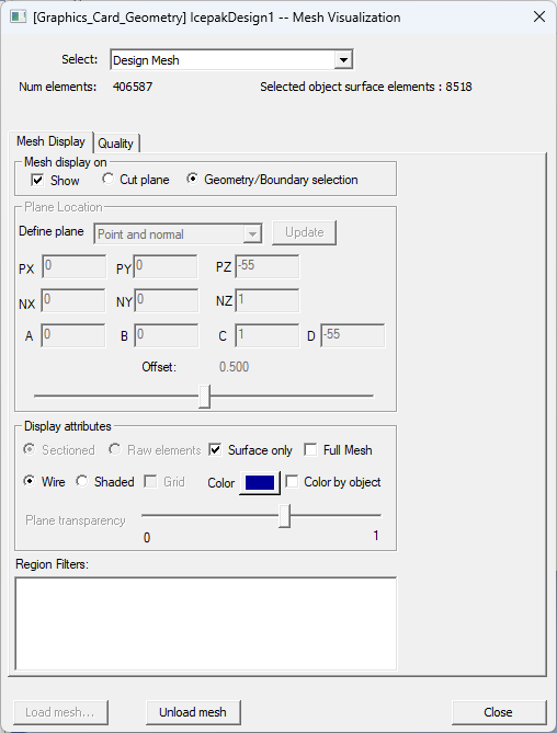
The following image displays the mesh for the selected object, which is the HEAT_SINK selected in the history tree.
Reduced Mesh and Full Mesh
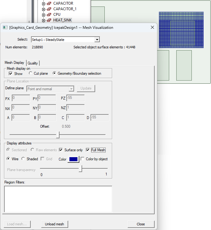
The following animated image illustrates how displaying reduced mesh compares to full mesh.
To display the mesh:
To inspect the mesh fully, use various combinations of the options available in the procedure below.
- Do one of the following:
- In the Project Manager, right-click Field Overlays and select Mesh Viewer.
Under Analysis, right-click a solution setup and select Mesh Viewer to view the mesh specific to that setup.
Note:If you modify the geometry of an object, the solution is invalidated, and the mesh is unloaded.
- From the Select drop-down list, select the mesh to display in the 3D Modeler window.Note:
If you select Design Mesh or a solution setup that is not linked to another design's mesh, the design mesh is displayed. If you select a solution setup that is linked to another design's mesh, the imported mesh is displayed.
- In the Mesh Visualization dialog box under Mesh display on, select Show and then Cut plane or Geometry/Boundary selection.Note:
Define settings under Display attributes to customize the mesh display.
- Under Plane Location, select an option from the Set Position drop-down menu:
- X, Y, or Z plane through center: Use the slider bar to move the plane cut.
- Point and normal: To move the plane cut, use the slider bar or enter values in the coordinate text entry fields and click Update.
- Select a face/plane: Select a face or plane.
- Coeffs (Ax + By + Cz = D): Enter values in the A, B, C, and D text entry fields and click Update. Then, use the slider bar to move the plane cut.
- Horizontal - screen select: Select a point in the 3D Modeler window.
- Vertical - screen select: Select a point in the 3D Modeler window.
Note:If needed, select one or more pieces of geometry from the Geometry Filters list to display mesh only on the selected object(s).
- Use the 3D Modeler window viewing tools to inspect the mesh from various angles.