
Working with Ribbons
The ribbon is the rectangular area across the top of the application. It comprises various tabs, each one representing a subset of commands available from the menus. The initial set of tabs (Desktop, View, Simulation, Automation) offers commands for adding and opening projects, selecting solvers, configuring the Desktop display (window choice, size, and position), configuring the simulation environment, setting scripted Event Callbacks or General Options, and showing Automation features for recording and using scripts.

The initial workflow for local configuration and personal customization is:

Available ribbon tabs depend on the design type. After you open or add a project and insert a design, you see additional ribbon tabs appear. The visible tabs and features are those that are appropriate for the design type and solver.
The Desktop, View, Simulation, Automation, Minerva and Learning and Support tabs appear for all design types. Additional tabs appear as follows:
- For HFSS, Icepak, Maxwell, Mechanical, and Q3D designs, the Draw, Model, and Results tabs also appear:

- For an HFSS 3D Layout design, the Layout and Results tabs also appear:

- For Circuit and Simplorer designs, the Schematic and Results tabs also appear:
")
In addition to Desktop, View, Minerva and Learning and Support the ribbon tabs that are applicable to
- Simulation Tab – contains tools that allow you to run simulations, perform validation checks, and schedule and monitor tasks.
- Results Tab – contains tools for creating reports and viewing solution data.
- Automation Tab – contains tools that allow you to run and record scripts, show or hide ACT extensions (Windows only), and install PyAEDT (Beta).
Each tab contains features specific to the design type, and the general workflow is from left to right.

Note that workflow can vary depending on tasks at hand. For example, if you open a completed model in HFSS or use 3D components or the ACT Antenna Design toolkit (Windows only), you may not need the features of the Draw tab. If Validation on the Simulation tab identifies problems in a model, you may need to use the Modeler menu commands for Analysis and Heal, or use the Discovery link feature. For some tasks, such as assigning excitations or boundaries in HFSS, you must use the command menus, rather than the tabs.
Sizing the Ansys Electronics Desktop window affects the icons displayed on each tab, with priority given to the most used features.
For example, If you have inserted an HFSS project, the View tab displays commands appropriate for the active editor:

If you reduce the size of the Desktop window, the ribbon tabs become compressed. Fewer icons are shown, and available features are moved into drop-down menus rather than shown separately. The following example shows the View tab in a compressed state:

Other ribbon tabs are similarly compressed when the window size does not support the fully expanded arrangement of features.
The Learning and Support tab provides easy access to Technical advice, instruction, and examples on Ansys websites.
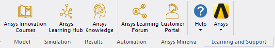
- Ansys Innovation Courses – opens a web page containing a wide range of Ansys Electronics Engineering courses using on-demand, self-paced video training and quizzes.
- Ansys Learning Hub – opens a web page with subscription based access to, virtual and self-paced learning across the Ansys Software portfolio.
- Ansys Knowledge – opens a web page to expert curated knowledge materials from FAQs to tutorials on simulation topics.
- Ansys Learning Forum – opens a web page to Ansys blog containing discussion and presentations from Ansys experts, partners and customers.
- Customer Portal – opens a web page to Ansys Product support.
- About Electronics Desktop - opens a dialog with version and release information, Ansys Electronics Desktop installed components, and licensing information.
IC Mode Layout Ribbon
In addition to exclusive tabs, HFSS 3D Layout contains two potential environments (i.e., General mode and IC mode). General mode typically opens by default. Different commands and options are available in each mode (e.g., after opening a GDSII file or selecting the IC layout from the Design Settings window (i.e., HFSS 3D Layout > Design Settings > Design Mode tab), the Layout tab will reconfigure to match the following screenshot).

The general workflow remains the same in both environments. Refer to Switching to IC Mode.