
HFSS 3D Layout S-Parameters
The S-matrix indicates what fraction of an incident voltage wave is transmitted or reflected at each port. The voltage wave is normalized with respect to the square root of the characteristic impedance of the port (e.g., a = V*Zo-1/2). If the characteristic impedance is completely real, the elements of the S-matrix are equivalent to the square root of the fraction of power transmitted or reflected. An S-matrix for a three-port structure is:
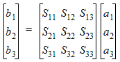
where:
- All quantities are complex numbers.
- ai represents the incident voltage wave at port i.
- bi represents the transmitted or reflected voltage wave at port i.
- The phase of ai and bi is the phase of the incident and reflected/transmitted voltage wave at t = 0:
Zai is the phase angle of the excitation voltage wave on port i at t = 0 (by default, it is zero).
Zbi is the phase angle of the reflected or transmitted voltage wave with respect to the excitation voltage wave.
- Sij is the S-parameter describing how much of the incident voltage wave at port j is reflected back or transmitted to port i (e.g., S31 is used to compute the amount of power on the port 1 excitation that is transmitted to port 3. The phase of S31 specifies the phase shift that occurs as the voltage wave travels from port 1 to port 3.).