
Fields Post Processing in HFSS 3D Layout
To analyze the radiated fields associated with a design, define a radiation surface over which the fields are calculated. Such a surface can be a boundary radiation surface, or a custom radiation surface that you define as an object face.
To plot near fields on a plane in HFSS 3D Layout:
- First define a near field setup. From the Project Tree, right-click Radiation and select Insert Near Field Setup > Plane
- From the Near Field Plane Setup window that opens, click OK. A new Plane setup appears in the Project Tree.
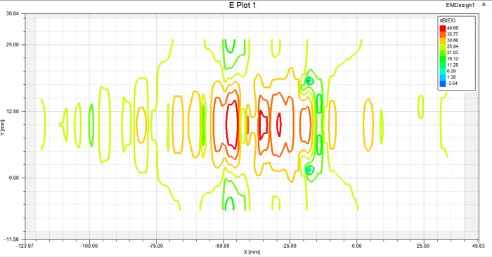
- From the Project Tree, right-click Results and select Create Near Fields Report, then select Rectangular Contour Plot or Data Table.
- From the Report window that opens, select "PlanarEM Setup" in the Solution menu and select a Plane setup in the Geometry menu. Enter "x" for the Primary Sweep and "y" for the Secondary Sweep, then click New Report. The plot appears and a new Radiation setup with the name of the selected Plane is created in the Project Tree.
For more information, see Getting Started with HFSS: A Ball Grid Array IC Package: Fields Post Processing.