
Solution Types
Before creating the design, you must specify the type of solution that you want HFSS to calculate. The following solution types are available:
- HFSS: The default solution type for HFSS designs.
- HFSS with Hybrid and Arrays: Adds the ability to define hybrid regions and arrays in the HFSS design.
- Transient: Used for calculating problems in the time domain. Transient solutions are applicable for simulations involving pulsed excitations (for example, lightning strikes).
- SBR+: Simplifies design creation for SBR+ users. HFSS can use Savant shooting and bouncing ray (SBR) technology to calculate the far field from current sources and defined geometry via one-way coupling. With this solution type, you do not need to specify explicit SBR+ Hybrid Regions.
- Eigenmode: This solution type provides results in terms of eigenmodes (or resonant frequencies) of a given structure. The solver provides the resonant frequencies as well as the fields at a particular resonant frequency.
- Characteristic Mode: This solution type is used for calculating the characteristic modes of a structure. The structure can be metal (conductor) or dielectric. The solution reports the number of modes, the characteristic angle and current (amp/meter), the modal significance and quality factor, and the voltage per port based on edit source weightings.
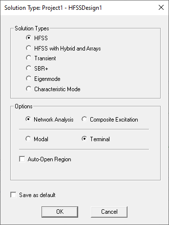
Solution Type Dialog Box for HFSS Designs
Solution Type Options
Three additional options are available for the HFSS, HFSS with Hybrid and Array, and Transient solution types only.
- Choose one of the following two options:
- Network Analysis: The default solution option for applicable solution types.
- Composite Excitation: This option provides a method for solving fields in a large frequency domain problem.
- Auto-Open Region: This option is typically used for antenna simulations. It automatically creates an open region and a predefined analysis setup for the project. You can select whether the region is Radiation, FE-BI, or PML. This option simplifies the design process. If you do not choose Auto-Open Region, you must create an air box and then assign a radiation boundary, either manually, or using the Create Open Region command.
Two additional options are available for HFSS and HFSS with Hybrid and Array solution types only.
- Choose one of the following two options:
- Modal: This option yields S-matrix solutions that are expressed in terms of the incident and reflected powers of transmission line modes.
- Terminal: The default option for applicable solution types. This option yields S-matrix solutions that are expressed in terms of terminal voltages and currents. For simulations that deal with signal integrity, the Terminal solution option is preferred. Such problems generally include transmission lines with single wave or multiple conductors.
Modal Option versus Terminal Option:
If HFSS is used to model a pair of coplanar, parallel microstrip transmission lines, a driven modal solution yields results in terms of the even and odd modes that propagate on the structure, whereas a driven terminal mode solution generates the common and differential mode results.
HFSS Simulation Examples
The design below represents a terminal solution of a differential pair of vias. A pair of lines transition through circuit board vias to a pair of striplines on a lower layer. The two microstrip lines and the striplines are each assigned a terminal in the coupled microstrip port. The conductors are copper, and a radiation boundary is applied to the air box. The design was solved at 4.38 GHz, and the electric field plots on the surfaces of the wave ports with terminals are shown in the following figure:
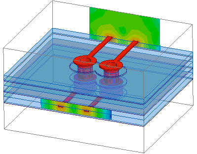
Terminal Solution of a Differential Pair of Vias
The following figure represents a modal solution of a connector between a coaxial and microstrip line:
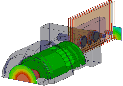
Connector between Coaxial and Microstrip Line
The following figure demonstrates a 3D finite element transient simulation of a lightning strike on a helicopter. Large currents flow through the aircraft skin generating electromagnetic field with the potential to damage sensitive equipment within. By using a transient simulation such challenges can be predicted early in the design phase saving costly empirical testing.
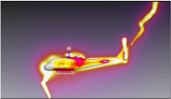
Lightning Strike Simulation of a Helicopter