Using Auto-Open Region for the HFSS Driven Solution Type for Antenna Designs
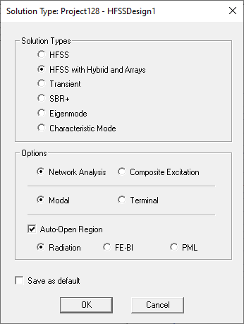
In Auto-open region mode, the workflow eliminates as much as possible the required interactions from a user and allows you to get to a robust solution quickly. It is intended for those who do not want to worry of the region and the exterior radiation boundaries. The option is available for HFSS Driven types for the modal, terminal and transient solution options. You can save this option as a user default.
In an open problem, an air volume encompassing the outer radiating surfaces is modeled by a surrounding object. Radiation boundary conditions (ABC, PML or FEBI) are assigned to the outer radiating surfaces to absorb all outgoing waves
If you have selected Auto-Open Region, HFSS automatically creates the region object or PML objects, the radiation boundaries or hybrid region according to your selection as Radiation, FE-BI, or PML, though these objects are hidden (not shown in the Project tree or History tree or listed in the Visibility dialog) unless you subsequently uncheck Use Auto-Open Region. In the case of PML, the PML Materials are hidden with Auto-Open (not listed under the Definitions>Materials folder in the Project tree), unless you subsequently uncheck Use Auto-Open Region. Rechecking Use Auto-Open Region leaves the PML for the previous auto-open is still visible.
Selecting Use Auto-Open Region also creates a Solution Setup called Auto1.

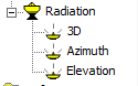
Selecting Use Auto-Open Region also creates three far field setups, as follows:
- ‘3D’ is a full sphere, Phi = 180 to 180 step 2, Theta = 0 to 180 step 2
- ‘Elevation’ will be Phi = 0 to 90 step 90, Theta = 180 to 180 step 1
- ‘Azimuth’ will be Phi = 180 to 180 step 1, Theta = 90 to 90 step 0
HFSS applies the most appropriate out-of-the-box settings based on the geometries and the operating frequency. You do not need to (and cannot) edit these settings directly.
This mode restricts the design to a single solve setup. You cannot manually create the region object, radiation boundaries or PML in this mode. Infinite ground plane, metallic IE region, primary/secondary (Lattice pair) and symmetry boundaries are also not allowed.
- Region padding for ABC is = lambda/3, for PML is lamda/4, and for FEBI (exterior as HFSS-IE Domain) = lambda/8 where lambda is the wavelength of the adaptive frequency of the solve setup. The region is automatically resized when users edit the solve setup's adaptive frequency. Initial meshes and solutions are invalidated when the region is resized. For multi-frequency or broadband setups the lambda is determined by the center frequency of the range.
- ABC assigned on the region object, with the user's selection of 1st order ABC or FEBI (HFSS-IE Domain)
- PML objects are created and resized automatically, invalidating solutions when a region is resized.
The region object is not listed in the command history, not visible in the View window and its definition cannot be edited directly. Similarly, the radiation boundary is not listed in the project tree, not visible in the View window and cannot be edited. This boundary is enforced to the lowest priorities.
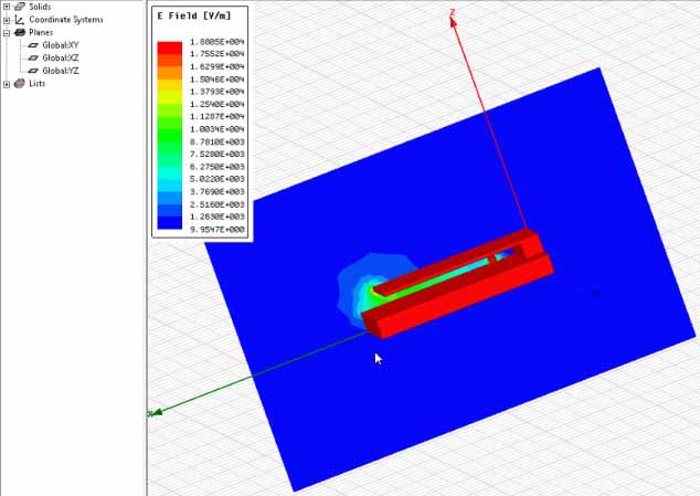
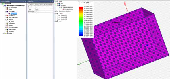
Because the region padding is automatically defined and not displayed, you cannot select faces from those regions for plots. However, you are able to create plots on the Global XY, XZ, or YZ planes.
- Changing a design from auto-open to non-auto-open preserves solution.
- Changing a design from non-auto-open to auto-open invalidates solution.
If you turn off the Auto-Open Region setting, the Radiation boundary becomes visible in the modeler window and as a Boundary called AutoOpen1 in the Project tree, and the region appears in the history tree.
In the case when you turn off the Auto-Open Region setting for a FEBI boundary, the Project tree shows a Hybrid region labeled AutoOpen1. 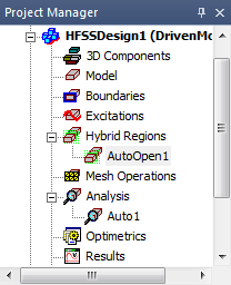
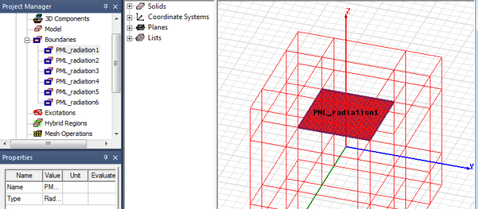
In the case when you turn off the Auto-Open Region setting for a PML boundary, the Project tree shows a set of PML_radiationn boundaries.