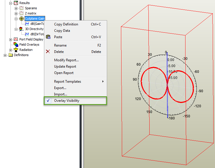
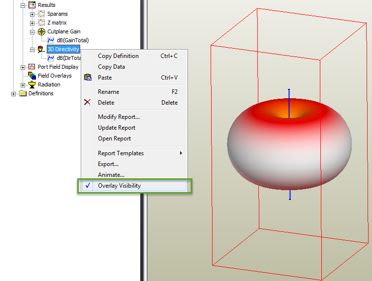
Overlay Visibility
This section describes how to plot radiation fields like Gain or Directivity right there on the geometry in the HFSS 3D Modeler window. Just right-click the plots under Results in the project tree and select the Overlay Visibility option from the short-cut menu to display the plots on the geometry.
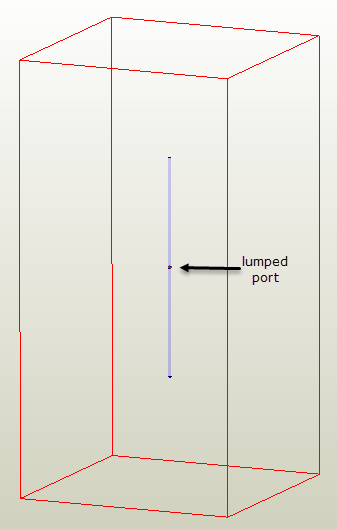
To illustrate this feature, consider a basic dipole antenna design shown in the following figure. The antenna is excited with a lumped port between the two nodes of the dipole.
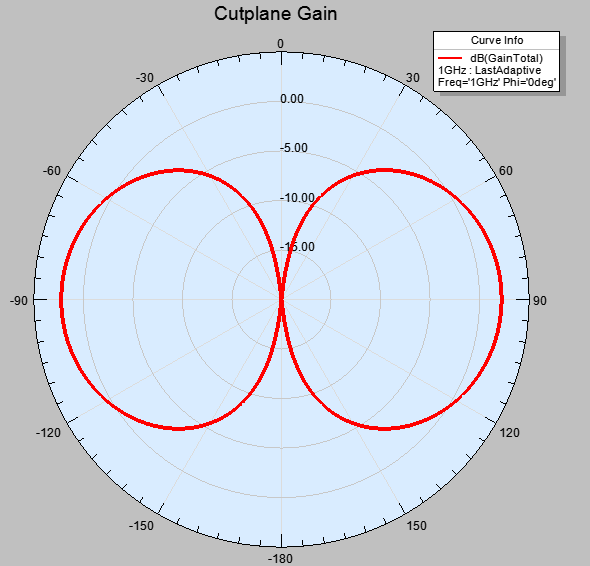
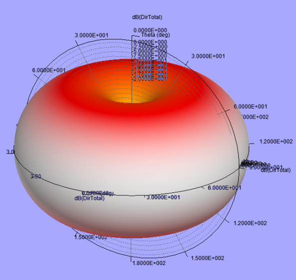
The antenna is simulated at 1 GHz. The generated Cut plane Gain and 3D far field plots can be displayed in their individual report windows. These are shown in the figures below.
You can also change the background color of these plot windows.
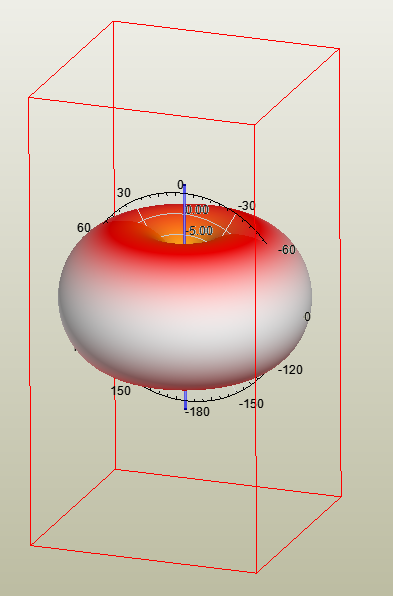
You can overlay these far field radiation patterns on the dipole antenna in the 3D modeler window by using a simple short-cut command. This overlay visibility feature can be very useful if you want to understand the orientation of the far field pattern relative to the structure of the antenna. You can directly apply the cut plane plots or the 3d polar plots right there on the antenna design as follows:
-
Right-click the plot under Results in the project tree and select the option Overlay Visibility as shown below.
This command overlays the plot on the antenna design.
The same one-step process also overlays a 2D radiation pattern as shown below.