Create 3D Component Coordinate Systems Tab
The list is populated with all the Coordinate Systems on selected objects. By default, only the Coordinate Systems used to define the object orientations are included. You can include Coordinate Systems created on specific model parts.
- Use the Include check box to include coordinate systems in the 3D component (selected), or to Exclude them from the component (cleared).
Alternatively, you can type a coordinate system Name into the text box and click the Include or Exclude button. Wildcards (? and *) are supported when you use this method, so you can change the inclusion state of multiple coordinate systems with similar names in a single operation.
- You can select any of the CS as the default handle. When this component is placed in assembly design, the handle CS is aligned to target CS in assembly design. Note that the handle CS can be changed after import; see Editing 3D Component Properties for more details.
- By default, the current working CS is designated as the default handle CS.
- The default handle CS must be included in the model (except for global).
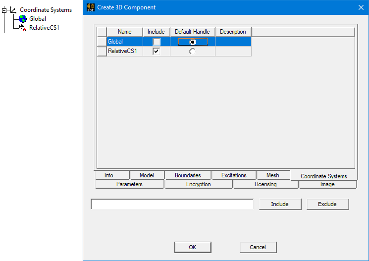
The specified default handle affects the orientation of the component upon insertion: