
When HFSS Needs Port Calibration (Deembedding)
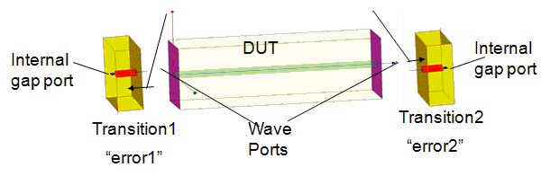
- If wave ports are used, HFSS does not require any port calibration.
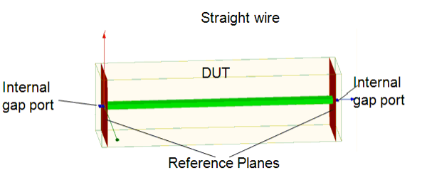
- If internal lumped ports are used, HFSS requires some port calibration (deembedding).
- If lumped or circuit ports are used, parasitic inductance of port geometry can be removed either through calibration or de-embedding.
Deembedding Extension/Transition Effects
Deembedded to the Discontinuity
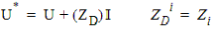
Deembedding Extension/Transition Z-matrix Method (Simplified Approximation)
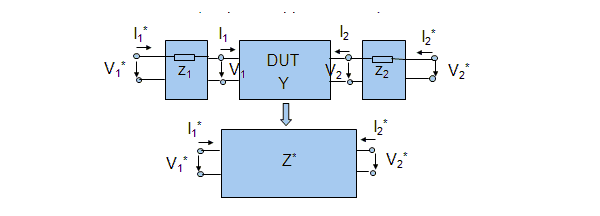
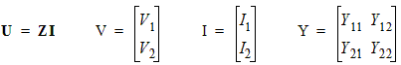
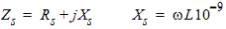
Impedance
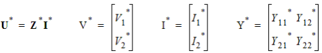
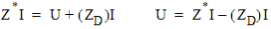
Matrix Z* is Measured/Simulated
Where Z1 and Z2 are known, then calculate/deembed Z matrix
Z Matrix Method
Measured/Calculated
|
|
|
(1) |
Dembedded
|
|
|
(2) |
|
|
|
(3) |
|
|
|
(4) |
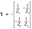
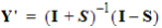
S matrix calculation from the series impedances to be deembedded

Formula
|
|
(5)* |
||
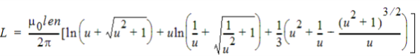
Where:
Input:
w = width of the lumped port [mm]
len = length of the lumped port[mm]
u = len/w
Output:
L[nH]
*From C.R.Paul, Inductance. Loop and partial, Wiley, 2010
And
|
|
|
(6) |
Currently, Rs
= 0
|
|
|
(7) |
|
|
|
(8) |
|
|
|
(9) |
|
|

|
(10) |
|
|
|
(11) |
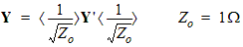
Z* is the global impedance matrix
Z is the Global impedance matrix after deembedding.