
Troubleshooting Mesh Failures
Common causes of mesh failures are improper geometry, incorrect design, or mesh settings. The following checklist can be used to address mesh failures and ensure that a suitable mesh is created to solve the problem:
- Select the model units in such a way that the smallest critical features in a design are at least 0.001 units long. Critical features include traces, gaps, vias, and contacts between objects.
- Override the Auto option on the Initial Mesh Settings panel to see if that helps. For example, set Classic Mesh as the initial mesh if the TAU Mesh fails and vice versa.
- Specify an appropriate value for the option Surface deviation (length) on the Surface Approximation panel (Manual Settings), if spline surfaces are present in the geometry. Typically, five percent of the thickness of the bounding box of the surface is a good choice.
- Either tighten or loosen the settings on the Surface Approximation dialog box to check if that helps.
- Select the Mesh Feedback tab on the Model Analysis dialog box to view the error log reported by the mesher. Go to Modeler > Model Analysis > Show Analysis Dialog > View Mesh Feedback to access this tab.
The HFSS mesher can automatically repair and correct a poorly translated and healed model to generate a reliable mesh. You can adjust the surface approximation settings if you want to further modify the corrections. The Profile reports when mesh repairs are made and the results of these repairs are displayed for every object in the mesh statistics panel.
The following sections provide troubleshooting tips to correct potential mesh failures on simple geometries:
Scenario 1:Model Resolution has Caused Significant Changes in Object Dimensions
The following figure illustrates a scenario where improper
MRL length can cause mesh failures. The geometry consists of a regular
polyhedron on the top of a box.
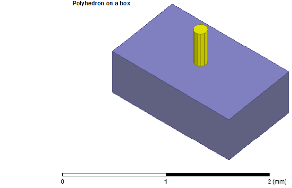
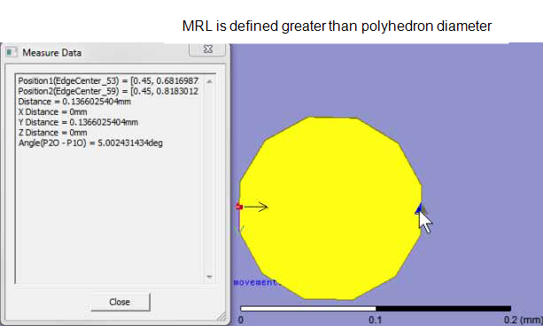
The
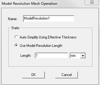
diameter of the polyhedron is 0.136 mm and the Model
Resolution Length defined for the polyhedron is larger than
the diameter itself as shown in the following figure.
HFSS generates the following warning messages:
Model Resolution has caused significant changes in object dimensions or contact between objects. Please compare the MRL set on the bodies with the dimensions of the bodies. Please ensure the unites selected such that the smallest critical features of the model are at least 0.001 units long. Specific details may be found in Modeler > Model Analysis > Show Analysis Dialog > View Mesh Feedback.
Geometry stitch failed. Failing back to backup process.
To diagnose the problem, first see the Model Analysis dialog box. For more details of the error type, select the Display Mesh Error Log check box.
For this particular geometry, a model resolution length of 0.045mm (one-third of the diameter of the polyhedron) created the correct mesh.
In general, select the model units such that the smallest critical features are at a minimum 0.0001 units long to address such warning messages. For a circuit board with a 1-micron trace width and vias, solder balls, bondwires, and gaps, each greater than 1 micron, the smallest critical feature is the trace; if the model is drawn in mm, the smallest critical feature can be 0.001 mm. However, if the model is drawn in centimeters, the smallest critical feature is 0.0001cm, which is way below the minimum permissible value 0.001. Such improper unit selections can cause mesh failures. Choose the units such that the entire solution domain is less than 1000 units.
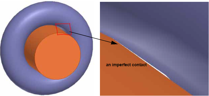
Scenario 2: Contact Area Change Too Large
Imperfect tangential contacts between curved surfaces
can cause mesh failures. In the following figure, the radius of the cylinder
is 0.1 mm, the major radius of the torus is 0.15 mm, and the minor radius
is 0.05mm.
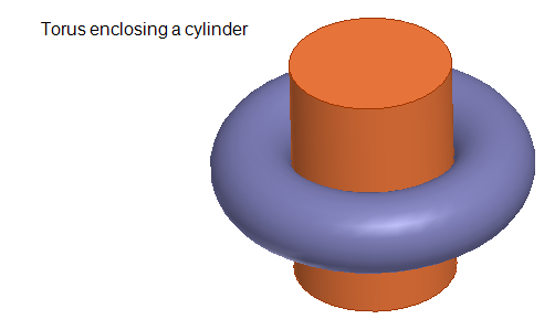
The
axis of the cylinder is slightly tilted relative to the axis of the torus
causing significant change in contact between objects.
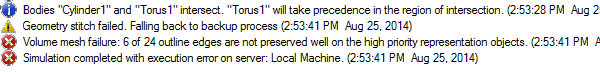
A
mesh cannot be generated for this incorrect geometry. When analysis of
this design is attempted, the following informational, warning, and error
messages are reported in the Message Manager window.
On the Model Analysis
dialog box, the last analysis status for each of the objects is listed.

For the simulation to complete successfully, the axis of the cylinder relative to that of the torus must be aligned properly.