Reference Conductors
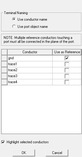
The Reference Conductorsdialog box contains a table that lists all the conducting objects used in a model. In this dialog box you will choose the conductor(s) that will act as reference. You can name terminals based on the name of their conductors or their associated ports.
We will depict a couple of scenarios that you may encounter while assigning terminals to conductors in your model. For both scenarios we will consider the same microstrip line with modifications to the model.
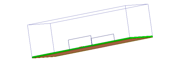
Scenario 1: Explicit Reference Conductor
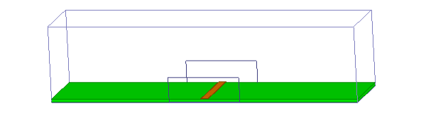
The following figure shows a microstrip line enclosed by
an air box. The model has an explicit ground plane that is orange in
color.
The
ground is an explicit object and so it will appear as a conductor in
the Reference Conductors for Terminals
dialog box when assigning terminals to the trace.
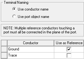
Select Ground as reference so that the terminal appears only on the Trace and not on the Ground.
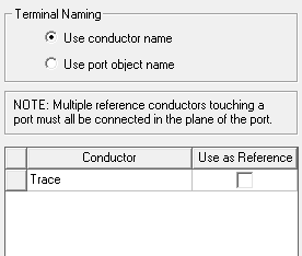
Scenario 2: Implicit Reference Conductor
The following figure illustrates the same microstrip line enclosed by an air box without the radiation boundary. This model does not have the explicit ground plane.
The solver treats the boundary of the air box as PEC because no other explicit boundary condition is applied to it. The air box acts as a reference conductor but will be treated as an implicit conductor that does not appear in the dialog box. In this case do not define the reference conductor as it is already assumed by the solver.