
HFSS SBR+ Technical Overview
Physical Theory of Diffraction (PTD) and Uniform Theory of Diffraction (UTD)
For SBR+ simulations, the Physical Theory of Diffraction (PTD) and Uniform Theory of Diffraction (UTD) physics enhancements can account for additional phenomenology not predicted by ordinary SBR due to truncation of uniform Physical Optics (PO) currents at sharp angular discontinuities (“wedges”) on metallic surfaces and blockage of SBR’s Geometrical Optics (GO) rays. PTD is a numeric correction to the scattered fields radiated by incorrect PO currents near wedges. UTD launches bundles of edge-diffraction rays from directly illuminated portions of each wedge along the Keller cone. Once launched, the UTD rays behave exactly like regular SBR rays, propagating according to GO and painting PO currents at each bounce that contribute to the scattered field. The UTD rays often illuminate portions of the SBR scattering geometry that are never reached by SBR GO rays launched directly from the field source.
The PTD and UTD wedge features are only deployed for metallic wedges with line-of-sight visibility from the source (Tx) location. If either adjacent surface of the wedge is non-PEC and not within the tolerance for PEC-like, or if the entire edge segment is invisible to the source, the wedge will be ignored in the SBR+ simulation and for visual ray tracing (VRT).
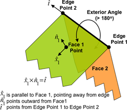
SBR+ Wedges
SBR+ wedges are required to enable PTD/UTD corrections. Wedges are extracted from metal surfaces if their exterior angle is larger than the Maximum Wedge Angle specified in SBR+ Wedge Settings or Wedge Settings. The default Maximum Wedge Angle is 225 degrees. Also, toggle on Include Sheet Edges to extract knife edges from open-ended sheets. When many wedges are extracted, PTD/UTD computations may be time consuming. The SBR+ wedges can be selectively filtered out using Apply Source Distance filter or Apply Box Filter, and PTD/UTD corrections are then applied only to the wedges that remain.
Physical Theory of Diffraction (PTD)
When SBR+ wedges are extracted from metal surfaces, SBR+ can apply a PTD wedge correction to improve the accuracy of the baseline SBR solution. Recall that SBR uses GO to extend PO to multiple bounces. The first-bounce solution of SBR is therefore traditional PO, with ray tracing used to determine which surfaces are lit. A limitation of this approximation is that it does not account for the distortion of surface currents in the vicinity of discontinuities in the geometry, such as sharp edges.
For example, consider a metal plate of moderate size in wavelengths. In the middle region, PO does a good job of approximating the currents. However, near the plate edges, PO assumes uniform currents up to the edge boundary. In reality, approaching the edge, current components perpendicular to the edges smoothly drop to zero while components parallel to the edges become very large. This localized PO inaccuracy is of little importance near specular scattering regions (i.e., near GO inter-bounce or exit ray paths in the near- or far-field) since the field results are dominated by the influence of the large area of currents over the plate interior where PO is accurate. However, the currents near the plate edges have a strong influence on diffraction in the shadow region and other regions far removed from specular scattering angles. Hence, while PO (and SBR) alone predicts diffraction in the shadow regions, it cannot be expected to consistently yield accurate levels of diffraction.
PTD theory was originally developed to address this very problem. The PTD wedge treatment is an asymptotic, coherently additive correction to PO that is designed to account for localized non-uniformity of currents near metal wedges and edges. It is somewhat analogous to the UTD correction to GO in this sense, except that the PTD correction to PO is milder than the UTD correction to GO; GO yields zero fields in the shadow region while PO always yields finite fields and already partially accounts for diffraction.
PTD was originally formulated as a correction term in the scattered fields rather than as a correction to the currents near edges that give rise to these correction fields. From the perspective of practical computation, the methodology was subsequently improved by casting PTD in terms of equivalent (artificial) edge currents running along the edges. These are sometimes referred to as incremental length diffraction coefficients (ILDCs) in the literature. One integrates these 1-D edge-axial currents along the actual path of the platform edges. For curved wedges, the equivalent currents are only based on local conditions that vary along the edge according to the changing incident and scattered field angles relative to the wedge geometry. From the standpoint of practical computation, the key benefit of using ILDCs is that they allow PTD to be applied to complex geometrical shapes encoded in 3-D CAD models. The implementation of the PTD wedge correction in SBR+ is based on this approach of equivalent, filamentary edge currents.
Users should be aware of a several limitations of the PTD wedge correction in SBR+. First, it can only be applied to metallic (PEC or PEC-like) wedges. There is no PTD correction formulation for dielectric wedges. SBR+ takes steps to ensure that the correction is not applied to wedges with one or two non-metal faces; the PTD correction is automatically skipped during the simulation when encountering wedges with non-conductive boundaries. Second, the correction is only applied to wedges that are directly illuminated by the Tx antenna, not edges indirectly illuminated via GO multi-bounce. Third, the PTD correction is only valid for field observation points on the order of a wavelength or more from the edge scattering point. This is because the correction is formulated in terms of 1-D equivalent (artificial) currents instead of a distribution of 2-D physical surface currents in the vicinity of the edge. This limitation has no impact on far-field results, but it can matter for near-field results when the observation points and Rx antennas get too close to a wedge in the CAD model. In fact, left to itself, the PTD correction based on equivalent currents becomes singular approaching the edge. To prevent this from happening, SBR+ automatically tapers the correction field generated by the equivalent currents at small distances from the edge. For example, at 1.0, 0.5, 0.2, and 0.1 wavelengths distance from a given edge, only 98%, 90%, 60%, and 28% of the correction is applied.
When a wedge consists of two flat faces meeting to from a common edge, the edge has finite axial extent. However, the faces are assumed by the PTD formulation to extend away from the edge without ending. This assumption limits accuracy when a source, wedge face, and observation angle/point are aligned.
Uniform Theory of Diffraction (UTD)
When SBR+ wedges are extracted from metal surfaces, the traditional GO rays can be augmented by another class of rays that are created by diffraction at these wedges. These rays are called UTD rays in SBR+, since they are governed by the uniform theory of diffraction at metallic wedges. UTD, formulated by Kouyoumjian and Pathak in 1974, is an extension of Keller's geometrical theory of diffraction (GTD). The coefficients of the diffracted rays in Keller's GTD exhibited singularities at the incident and reflection shadow boundaries. These singularities were removed by UTD, yielding a description of diffracted rays that is uniformly valid at all angles.
The UTD rays are an augmentation of GO rays, much like the PTD Wedge Correction is an augmentation of PO radiation. Without the UTD rays, only the regions of the CAD model that have a line-of-sight (LOS) or multi-bounce GO path from the transmitter are illuminated. This direct and indirect illumination is effected by the GO rays launched from the transmitter. With the addition of UTD rays, portions of the CAD model that do not have a LOS or multi-bounce GO paths to the transmitter can also be illuminated, improving the ray coverage on the CAD model. This type of indirect illumination is achieved when rays leaving the transmitter diffract at wedges (which are required to be in direct LOS of the transmitter, as they are for PTD wedge correction) in accordance with the uniform theory of diffraction. The resulting UTD rays reach previously shadowed points on the CAD model. It should be noted that the UTD illumination mechanism is not limited to shadow regions: UTD rays can also hit portions of the CAD model that are in the LOS of the transmitter.
The existence of a UTD ray is not guaranteed for every point on the CAD model. The defining property of a UTD ray is the minimum distance principle, as it is for a GO ray. An equivalent expression of this property is that a UTD ray leaving a wedge lies on the Keller cone at the diffraction point. The angle formed between the incident ray and the edge line at the diffraction point defines the characteristic half-angle of the Keller cone, whose cone axis is aligned with the edge. There may be portions of the CAD model that do not intersect any of the Keller cones defined by the transmitter and the existing wedges. There may also be blockage effects preventing the propagation of UTD rays to some regions. Conversely, some points on the CAD model may be illuminated by multiple UTD rays if there are valid UTD paths to those points through multiple wedges.
Once a UTD ray is launched from a wedge, it behaves in exactly the same way as other GO rays in the SBR algorithm. It gets reflected, transmitted, and absorbed at subsequent bounces, and either reaches the maximum number of bounces or escapes to infinity. However, the initial state of the UTD ray upon leaving the wedge depends heavily on the diffraction geometry.