
HFSS Antenna Design Toolkit
The HFSS Antenna Design Kit is a GUI-based utility which automates the geometry creation, solution setup, and post-processing reports for over 60 antenna elements. This tool allows antenna designers to efficiently analyze common antenna types using HFSS and also assists new users in learning to use HFSS for antenna design. All antenna models created by the design kit are ready to simulate in HFSS. (Note that on opening an HFSS-IE project, the project will automatically be converted to an equivalent HFSS project using IE Regions.) Simulations, sweeps, and 2D and 3D post-processing reports are automatically defined.
Parametric Antenna geometry:
- Easily modify parameters in HFSS after generating initial model.
- Facilitates parametric sweeps and optimizations.
Synthesis features for each antenna:
- Automatically generates physical dimensions for desired frequency when you use the Synthesis button.
- Provides starting point for new designs.
The HFSS Antenna Design toolkit is implemented in Ansys ACT.
To launch the Wizard:
- Click View>Extensions command to open the Extensions window.
- Click Wizard to open the ACT Start Page.
- Click Execute Wizards to change the show HFSS Antenna.
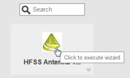
The HFSS Antenna wizard displays.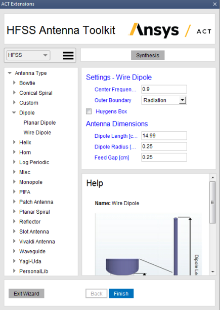
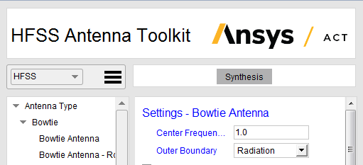
Using the HFSS Antenna Wizard
The HFSS Antenna Wizard contains areas for selecting the design type, selecting the category and type of antenna, and a help section that illustrates the selected antenna.
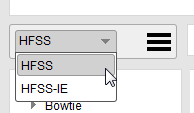
- Select the type of antenna as HFSS or
HFSS-IE from the drop-down menu.
- You then select the Antenna type and category
from the library list. You can show or hide the categories under each antenna type by clicking the arrow icons.
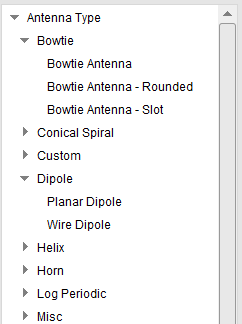
The choices are:
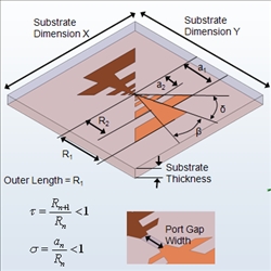
- Bowtie, with three types:
Bowtie Bowtie Rounded 
Bowtie Slot - Conical Spiral with three
types:
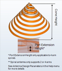
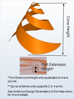
Archimedean Spiral Log Spiral 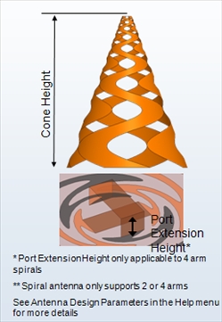
Sinuous Spiral - Custom with two types:
GPS - Ceramic UHF Probe - Dipole
with two types:
Planar Wire - Helix, with five types:

Axial Mode Continuous Taper 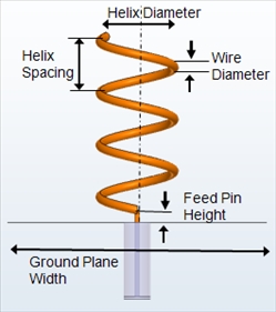
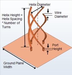
Normal Mode Quadrifilar - Open 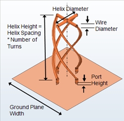
Quadrifilar - Short - Horn, with eight types:
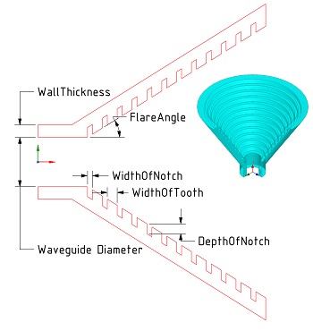
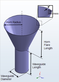
Conical Corrugated Horn Conical 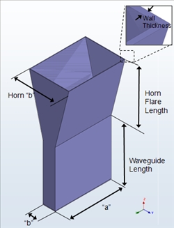
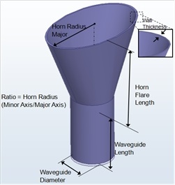
E-Plane Sectoral Elliptical 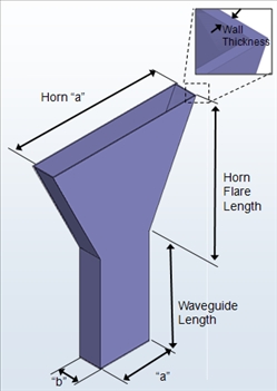
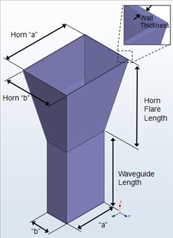
H-Plane Sectoral Pyramidal 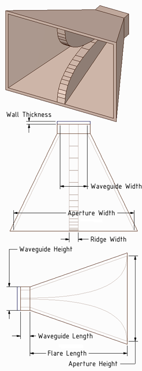
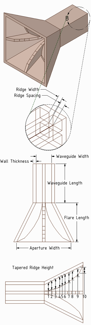
Pyramidal Ridged Quad Ridged - Log Periodic, with three types:
Toothed Trapezoidal 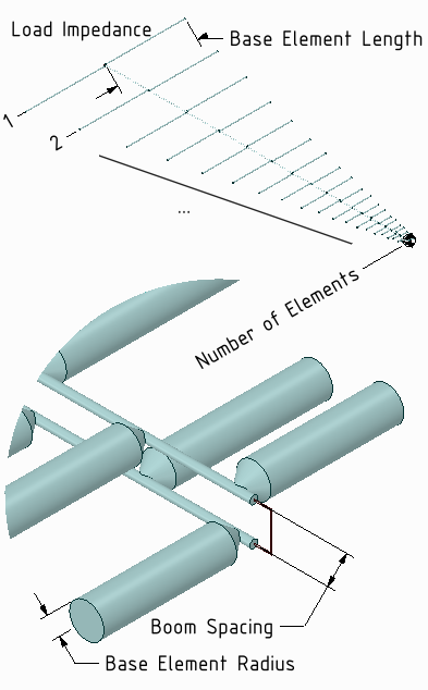
Log Periodic Dipole Array - Misc, with two types:
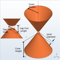
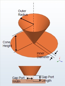
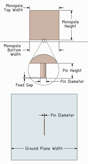
Bicone Discone - Monopole, with six types:
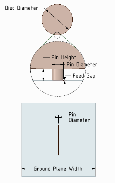
Blade Circular Disk 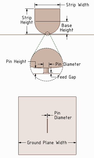
Elliptical-Base Strip Vertical Trapezoidal 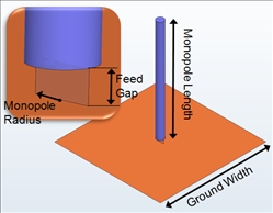

Wire Infinite Ground - PIFA, with three types:
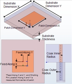
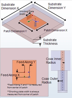
Shorting Pin Shorting Plate 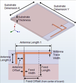
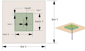
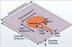
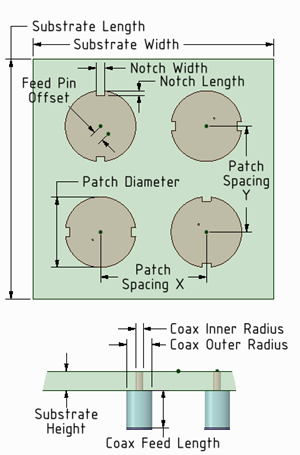
Planar Inverted-F - Patch Antenna, with eight types:
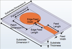
Elliptical-Edge Fed Elliptical-Inset Fed 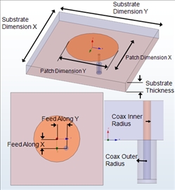
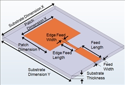
Elliptical-Probe Fed Rectangular-Edge Fed 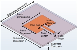
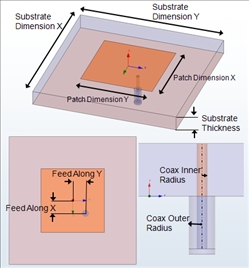
Rectangular-Inset Fed Rectangular-Probe Fed 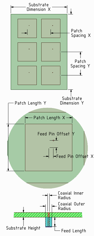
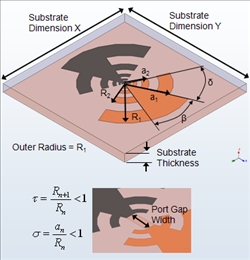
Rectangular-Probe Fed MxN Patch Array Sequentially Rotated 2 by 2 Patch Array - Planar Spiral,
with six types:
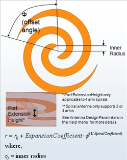
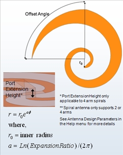
Archimedean Log 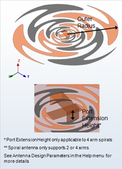
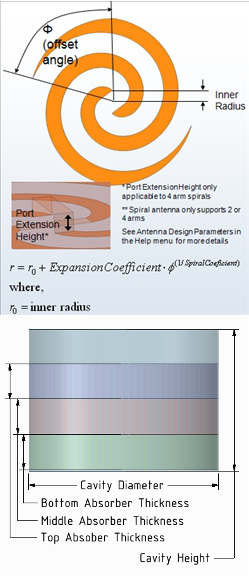
Sinuous Archimedean with Absorber-Lined Cavity Backing 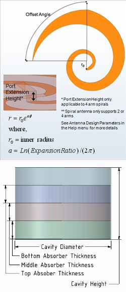
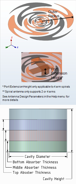
Log with Absorber-Lined Cavity Backing Sinuous with Absorber-Lined Cavity Backing - Reflector, with four types:
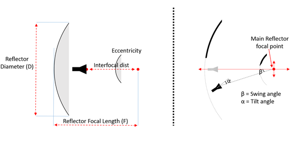
Cassegrain 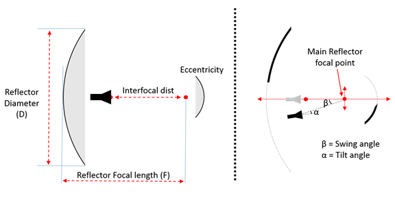
Gregorian 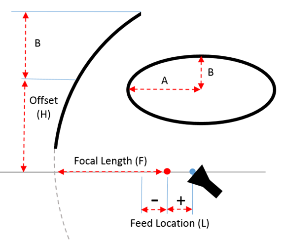
Parabolic 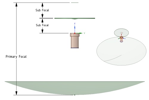
Splash Plate - Slot Antenna, with four types:
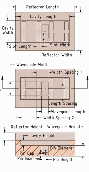
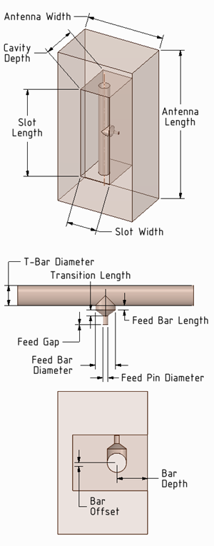
Cavity-backed Slot Antenna Array Cavity-backed T-bar-fed 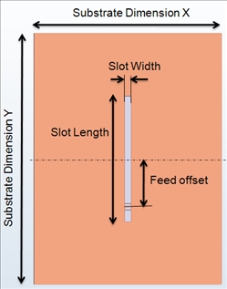
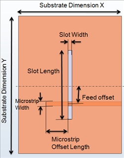
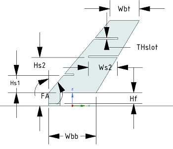
Gap Feed Microstrip Feed - Vivaldi Antenna,
with two types.
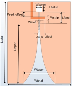
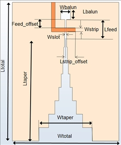
Vivaldi Stepped - Waveguide,
with three types:
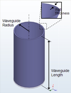
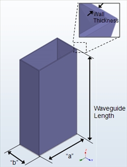
Circular Rectangular 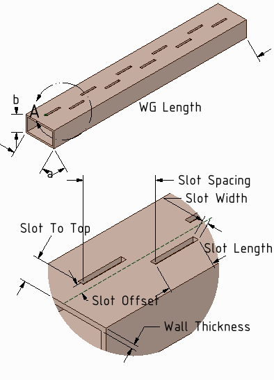
Rectangular Waveguide Slot Array - Yagi-Uda,
with two types:
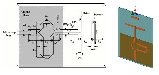
Quasi-Yagi 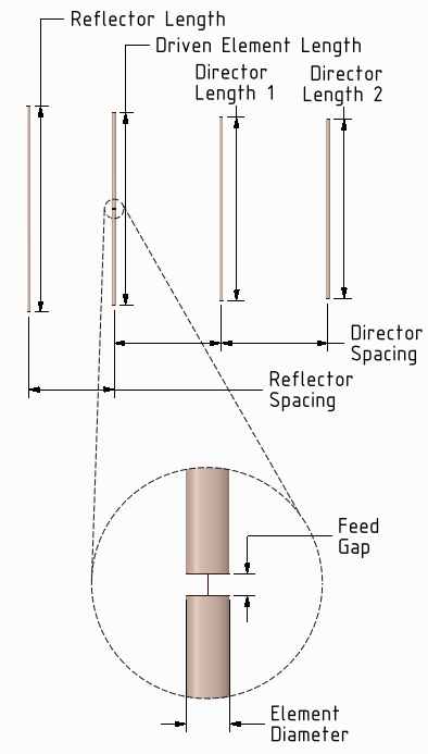
Wire Yagi-Uda - PersonalLib, with any that you have added,
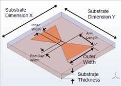
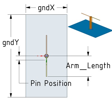
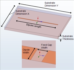
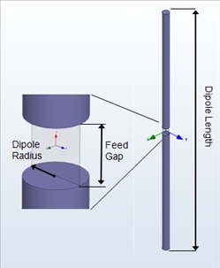
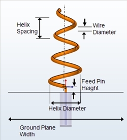
- When you have selected the antenna, double-click to display its settings, parameters and the help showing the antenna and where the parameters apply.
The Settings
for each antenna include frequency and various parameters. For HFSS Design types (not HFSS-IE), you can specify the Outer Boundary and check Huygens box. Antenna
dimension parameters vary depending on antenna selected. Other dimension parameters for Feed, Slot, Ground plane, Substrate dimensions and such vary somewhat depending on the antenna Type selections. Depending
on your window size, you may need to use scroll bars, or resize the window
to see all the selections. The Help figure will help you visualize how
each parameter applies.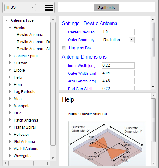
- If you change the Center Frequency parameter and select Synthesis, the antenna dimensions are automatically updated in order to operate at that frequency.
- When you have made your selections click Finish.
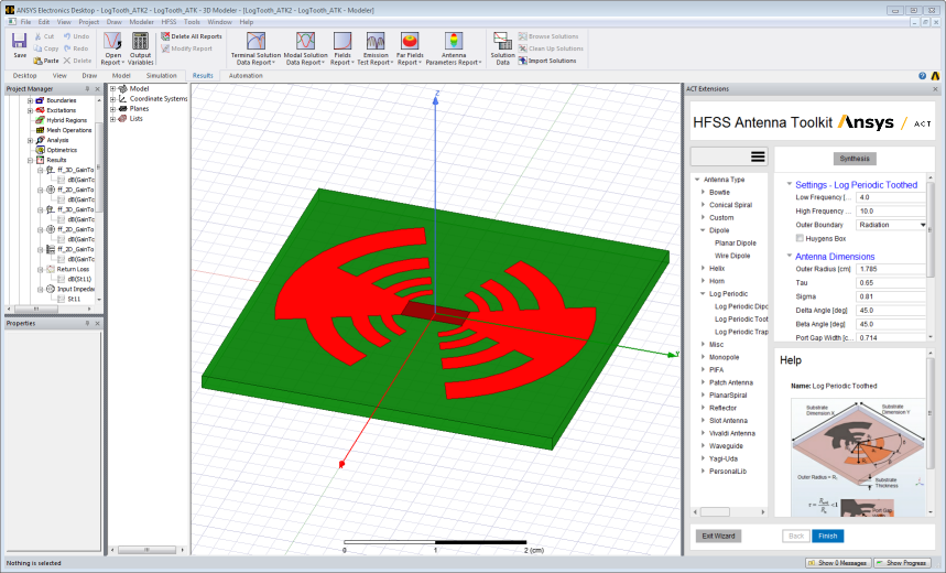
The Antenna Toolkit then creates a project with
the antenna design. It displays a message that it is "Executing current step" and some animation indicates progress. As the synthesis completes, the Project tree shows the added Boundaries, Excitations,
Hybrid Regions (if specified). It also generates a Solution setup and
sweeps specific to the antenna type, as well as a range of predefined
2D and 3D plots, a Port Field Display, and 2D and 3D Radiation Spheres.
The Design Properties lists all of the local variables. And the History
tree shows the objects created . You can then run analyses and view results.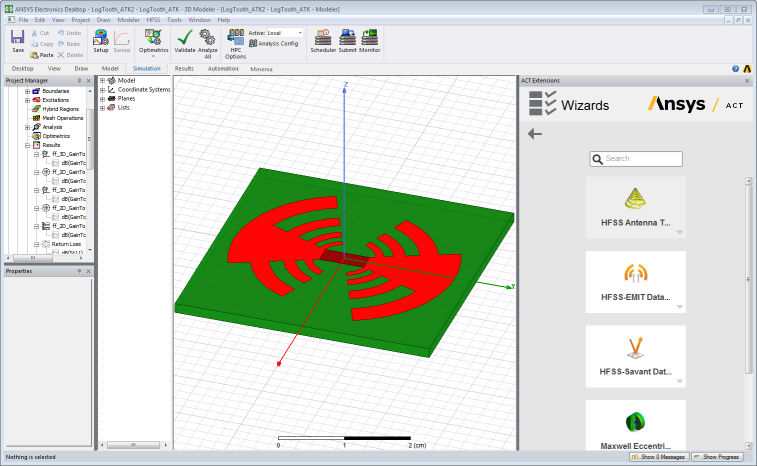
Add Antenna from 3D Component Libraries Button
The Add Antenna button opens a dialog that lets you browse and select from antennas in the 3D Component library (that is, with a *.a3dcom suffix), including example antennas provided and those design you may have created or imported and convert to 3D components.
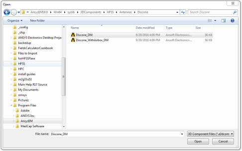
When you select a 3D component file and click Open in the browser, the component is temporarily displayed in the Modeler window, and the Add Antenna dialog displays. Here you can see settings, properties, and documentation, and can click OK to continue.
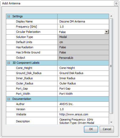
After you click OK, the antenna is listed under PersonalLib>Custom at the bottom of the Antenna Type list:

One advantage for adding antennas to the Antenna Design Toolkit PersonalLib is that when you then select the antenna from the toolkit library, you get the automated the geometry creation, solution setup, and post-processing reports for over 40 antenna elements.