
Ferrite Permeability Tensor in HFSS
Gyrotropic Permeability
The ferrite capability of HFSS is based on the Polder susceptibility tensor small signal approximation of the Landau-Lifshitz equation of motion of a magnetic dipole in a uniform bias field [1] [2].
The formulas are given in CGS units. The formulas assume a saturated ferrite sample, and both Ms and Ho should be set to 0 for the unbiased demagnetized case.
| 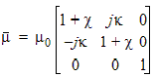 | (1) |
Where
|  | (2) |
|  | (3) |
With
|  | (4) |
|  | (5) |
|  If Ms is not = 0 this tensor
overrides any value of permeability | (6) |
And
|  | (7) |
ge is half of the electron charge to mass ratio and gl is the Lande g factor. The Lande g factor is typically between 1 and 2, with 1 corresponding to orbital angular momentum and 2 for spin.
If the ferrite has magnetic losses, we replace wo by wo + jwa where a is computed from the ferromagnetic resonance linewidth:
|  | (8) |
When HFSS assembles the finite element matrices for ferrite materials it computes the permeability tensor, 1, based on several different inputs:
- Frequency - w
- Material properties - all of which are specified in the material manager
- Saturation Magnetization - Ms
- Lande g factor - gl
- Loss factor - computed from DH and fFMR
- Magnetostatic bias field - Magnetic Bias source, either:
- Uniform bias - Ho and direction specified in the interface
- Non-uniform bias - Ho
and local tensor
 direction determined by the magnetostatic field solution from Maxwell3D.
When the Magnetic Bias source is nonuniform, the permeability tensor
will be different in each ferrite tetrahedron.
direction determined by the magnetostatic field solution from Maxwell3D.
When the Magnetic Bias source is nonuniform, the permeability tensor
will be different in each ferrite tetrahedron.
References
[1] David Pozar, Microwave Engineering, Addison-Wesley, 1990.
[2] Daniel D. Stancil, Theory of Magnetostatic Waves, Springer-Verlag, 1992.