Assigning Voltage Sources
A voltage source in HFSS can be defined on a surface located anywhere in the 3D problem space. Typically the source is placed on a surface between two conductors such that a user defined total voltage is maintained between the conductors. Voltage source is used when the feed structure is very small compared to the wavelength and a constant electric field may be assumed across the feed points; in this case, HFSS assigns a constant electric field across the gap on which you specified the voltage.
For more information, see Voltage Source in Technical Notes.
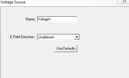
- Select the object face to which you want
to assign the voltage source, and click HFSS>Excitations>Assign>Voltage
to display the Voltage Source
dialog box.
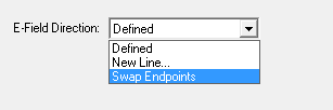
- Specify the direction of the electric
field by drawing a vector.
When the source is selected, an arrow indicates the direction and a letter v indicates the type of source.
Note:For Transient Solution types, you also designate sources as Active and Passive.
Port sources are created and solved with unit magnitude and 0 degree phase. They can be scaled within the Edit Sources dialog.
The E-field direction can be reversed from the Voltage Source dialog box.