
Assigning Symmetry Boundaries
For Driven Modal or Eigenmode Designs
A symmetry boundary represents a perfect E or perfect H plane of symmetry. Symmetry boundaries enable you to model only part of a structure, which reduces the size or complexity of your design.
To assign a Finite Conductivity boundary:
- Select a surface on which to assign the
boundary and click HFSS> Boundaries> Assign> Symmetry to bring up the Symmetry
Boundary dialog box.
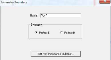
- Select the type of symmetry plane the boundary represents: Perfect E or Perfect H.
- Click Impedance Multiplier.
If the design includes a port, you must adjust the impedance multiplier or the computed impedances will not be for the full structure.
The Port Impedance Multiplier dialog box appears.
- Type a value in the Impedance Multiplier box, and then click OK.