
Assign Floquet Ports
This section describes how to assign Floquet Ports on the unit cell after you define the Primary and Secondary boundaries. To assign the Floquet port perform the following steps.
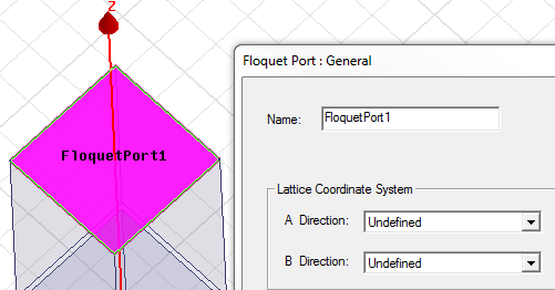
- Floquet ports must be placed along the Z axis, as shown. Select the top
face of the unit cell, right-click, and select Assign> Excitation>
Floquet Port from the shortcut menu.
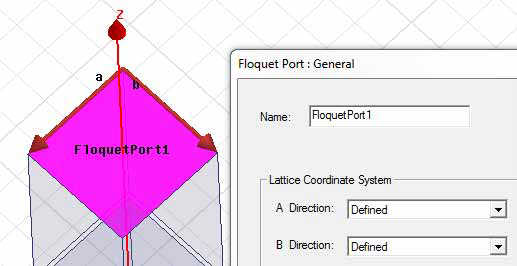
- Specify the A and B directions for the Lattice coordinate system. These define the
periodicity of the planar lattice. The vector arrows must start and end at points on the
face of the Floquet port and must have a common initial point.
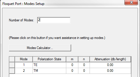
- The Modes Setup window displays a field for the Number of Modes,
a button for access to the Modes Calculator, and a table.
- On the post processing panel, if needed, the deembed distance can be specified.