
Align Modes Using Integration Lines
This option is for advanced users working with non-standard
waveguides which may have degenerate modes. First we will investigate
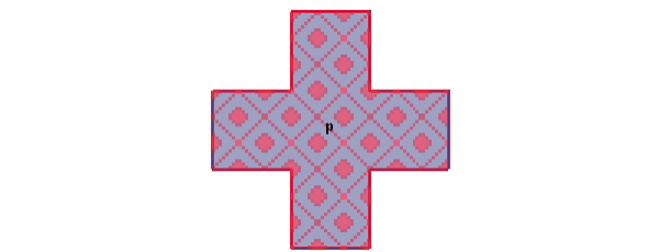
the fields for a wave port assigned on the surface of a symmetric cross-waveguide
(shown below) using the default settings on the General
tab of the Wave Port
dialog box. (Set mode polarity using integration
lines) for 2 modes. No integration line is defined.
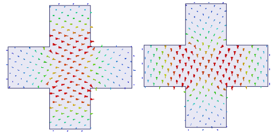
The solver arbitrarily assigns the polarity for the modes 1 and 2.
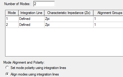
Any combination of degenerate modes results in just another combination of degenerate modes. There is no uniqueness in the orientation of the modes. To get a unique orientation advanced users can select this option Align modes using integration lines and define the integration lines appropriately. Prior knowledge of the mode pattern is necessary before you define the Integration Lines for mode alignment. You cannot draw the integration lines randomly. They are extremely important to get the mode alignment that you want. See the integration lines 1 and 2 defined on a port face shown below and the settings in the Modes sub-panel.
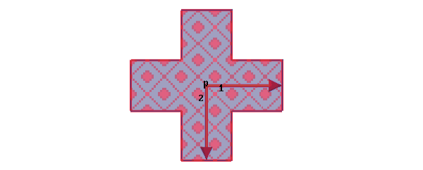
Alignment Groups
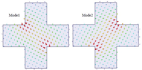
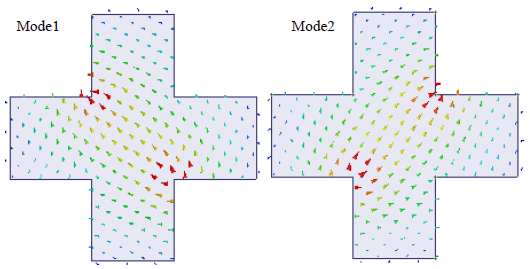
This column appears only when you select the option Align modes using integration lines. The modes that have the same Alignment Group number are degenerate. To help the solver choose which modes are degenerate you must assign the Alignment Groups. When you set the alignment group numbers the solver accumulates the modes of a specific group number and causes each mode within that group to have a positive voltage along its own integration line and zero voltage along all other integration lines. For example, defining integration lines 1 and 2 at right angles to each other for the port face (shown above) will cause the modes to be aligned as illustrated in the following figures.
Suppose you want the modes to be aligned along the integration lines 1 and 2 defined diagonally as shown in the following figure.

According to this definition of the integration lines, the solver aligns the modes within a given group (1 in this case) such that Mode n has a positive voltage along integration line n and zero voltage along all other integration lines.
For more information, see Mode Alignment.