
Adding a Solution Setup for Transient Solutions
When you specify the Transient solution type, you also specify the focus of this setup as either Transient Network Analysis or Transient Composite Excitation. The Transient Network Analysis setup includes an Input Signal tab, as shown in the figure. If the model contains a radiation boundary, the setup includes a Radiated Fields tab.
To add a Solution Setup for a Transient design:
- Click HFSS>Analysis Setup>Add Solution Setup to open the Transient Setup dialog with the General tab selected.
- Optionally check Import Mesh for mesh linking.
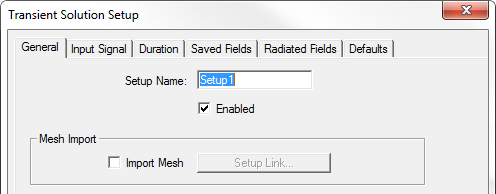
Otherwise, the mesh for the transient simulation is generated by a regular frequency-domain simulation. For that simulation, the software decides on the appropriate frequency at which to perform the adaptive passes. It uses mixed element orders and the iterative solver.
- For Adaptive solutions, you can specify:
- Maximum Number of Passes
- For Device characterization solutions, you specify a Maximum Delta S.
For Field Visualization solutions, you specify a Maximum Delta Energy for convergence per pass.
- For Transient Solver, select Hybrid (the default) or Implicit.
- The Hybrid solver is based on the explicit-implicit discontinuous Galerkin time domain method. It is more efficient for electrically large problems. If the GPU is enabled, only the explicit part of the hybrid solver is running and being accelerated by GPUs. For more information, see Technical Notes: Transient Solution Theory.
- The implicit solver is based on the finite element time domain (FETD) method with an implicit time stepping. Change the setting to Implicit for cases which the Hybrid Solver may not perform optimally. This typically refers to structures which are discretized into a small number of tetrahedrons but the required time step for the Hybrid becomes extremely small hindering the performance. Consequently, it takes longer for the simulation to finish. Furthermore, the Implicit Solver is in general better suited for low frequency analysis of electrically small structures with small vias, thin wires, thin slots, narrow gaps, and thin dielectric/metal plates. For more information see Technical Notes: Transient Implicit Solver.
- For a Transient Network Analysis solution, select the Input Signal tab to create a time profile.
- Select the Duration tab to specify the simulation stop criteria.
- Use the Saved Fields tab to select the face or object lists for which to calculate fields. By checking the boxes you can enable the Start saving fields time, and Save fields at interval. When you select an object list, you can also specify the Maximum Number of Samples.
- If your design includes a radiation boundary, you can select the Radiated Fields tab to if you intend to view radiated fields.