Custom Filters
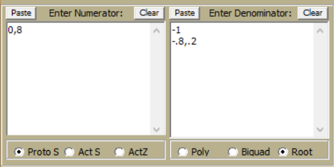
FilterSolutions provides the capability to create the filter based upon an existing Laplace Transform by selecting Custom in the Filter Type group box. Before selecting "Custom", have the implementation method already selected. If the Laplace Transform is a prototype, have the desired cutoff frequency and bandwidth already selected as well. Staged filters may be created by placing desired poles and zeros into the Custom Filter form entries.
Prototypes
A prototype transform is a low pass filter with a cutoff frequency of 1 radian per second. If Proto S is selected in the Custom Box, FilterSolutions will transform to the desired high pass, band pass or band stop filter, and provide frequency scaling prior to generating the passive or active filter. The user must enter pass band frequency, band width, and filter class.
Actual, S Transform
If Act S is selected along with S Trans in the lower left, FilterSolutions will set the magnitude of the filter, and generate a digital or analog circuit filter based upon exactly what was entered. It is important to note that not all transfer functions are realizable in passive circuit form, especially when the load and source resistors are equal. FilterSolutions will not generate band pass or band stop passive filters from actual Laplace transforms.
Actual, Mag Freq
If Act S is selected along with Mag Freq in the lower left, FilterSolutions will use an RMS error optimization algorithm to generate a digital or analog filter. Minimum and maximum transfer function stage Q may be entered as well as the number of transmission zeros and frequency limits for transmission zeros. Only low pass and high pass filters are permitted. FilterSolutions automatically detects low pass and high pass entries.
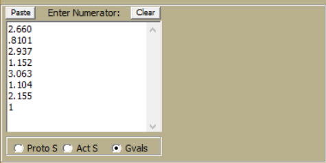
G Values
G values are the low pass, all pole prototype element values. These are used frequency as the starting point in microwave filter design. Select Gvals to enter a string of G values. G value strings must be terminated, that is, they must include the source resistor (Go) and the load resistance (G(n+1)). For equally terminated filters, Go and (G(n+1)) are both one (1.000).
Digital
If Act Z is selected, FilterSolutions will assume that a Z transform has been entered and will output frequency and time traces and pole zero plots for the entered Z transform.
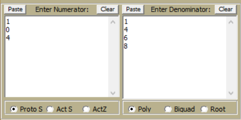
Formats
When entering transforms in polynomial form, enter the polynomial in descending powers.:
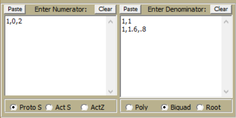
When entering biquads, use commas to separate biquad terms. Enter one biquad per line. The term "Biquad" as applied to this custom panel refers to any polynomial or order 2 or less.
When entering roots, use commas to separate real and imaginary part. Enter only one root per conjugate pair.
Since roots do not contain any gain information, FilterSolutions will attempt to estimate the gain, but this estimated gain may not be what is expected by the user. If not satisfied with the gain from transfer functions generated from roots, it will be necessary for you to use the biquad or poly selection instead.
G Values
When entering G values, start with Go at the top, and G(n+1) At the bottom. Below are the entries for a 6th order Chebyshev with 1dB of passband ripple. Note that Go is the normalized source resistance of 2.660.