
TRL Microstrip Transmission Line
|
Keyword |
Default |
Unit |
Description |
|
W |
Req (Phys) |
m |
Conductor width |
|
P |
0 |
m |
Physical length of transmission |
|
Z0 |
Req (Elec) |
ohm |
Transmission line impedance |
|
E |
0 |
deg |
Electrical length of transmission
|
|
Frequency |
0 |
Hz |
Analysis frequency |
|
ER |
Req |
|
Relative dielectric constant |
|
H |
Req |
m |
Substrate thickness |
|
HU |
40*H |
m |
Cover height above substrate |
|
TAND |
0 |
|
Dielectric loss tangent |
|
RGH |
0 |
m |
Rms surface roughness |
|
MSAT |
0 |
Gauss |
Saturation magnetization (4pMs) |
|
MREM |
0 |
Gauss |
Remnant magnetization (4pMr) |
|
TANM |
0 |
|
Magnetic loss tangent |
Synthesis and Analysis
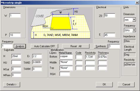
- For synthesis of microstrip transmission lines, the parameters Z0, H, and ER must be entered prior to clicking Synthesis. The width, W, is computed.
- For analysis, the parameters W, H, and ER must be entered prior to clicking Analysis. The impedance, Z0, is computed. The frequency is used if entered; otherwise, 0 Hz is used in the calculation.
- Conversion from electrical length, E, to physical length, P, can be performed by entering values for E and Frequency. Click Synthesis to compute P. Similarly, to convert from physical length to electrical length, enter values for P and Frequency, and click Analysis to compute E.
Dielectric Substrates
A dielectric substrate is defined by the parameters H, ER, and TAND. The substrate is assumed lossless unless TAND is specified and greater than zero.
Magnetic Substrates
- A magnetic substrate is defined when the MSAT and MREM parameters are given. The demagnetized substrate case occurs when MSAT > 0 and MREM = 0 (default). The partially magnetized substrate (including the fully magnetized, saturated, or latched substrate case) occurs when MSAT and MREM > 0, but MREM £MSAT.
- The direction of magnetic bias is assumed to be in the direction of wave propagation; that is, perpendicular to the transverse field.
- The magnetic loss tangent, TANM, can be specified to account for losses in the magnetic substrate. It is similar to the dielectric loss tangent, TAND, and its loss is added to find the total loss of the substrate.
- The minimum frequency of analysis must be greater than the gyromagnetic frequency:
- f > 2.8 (MHz/Gauss) ´ MSAT (Gauss)
- where the constant of 2.8 MHz/Gauss comes from the gyromagnetic ratio (g/2p).
- References 23-25 document propagation on magnetic substrates. In particular, the formulations by Pucel and Massé have been utilized in the program.
Conductor Metalization
- Conductor specification is performed in the Metalization control group. If the conductor is not specified, the conductor loss is zero and no thickness corrections are made to the line’s propagation characteristics. Up to three conductors of different metal and different thickness can be specified.
- Metalization rms surface roughness, RGH, can be specified for additional conductor losses due to imperfect metal surfaces. RGH is specified in terms of rms variation from an ideal flat surface.
Sweep Options
Parameters that can be swept for the microstrip transmission line are:
Frequency
Width, W
The order shown is the order used to generate output data when multiple parameters are swept simultaneously. See the Sweep Entries topic for further information.
Limitations
To maintain accuracy, the following limitations should be followed:
0.01 £W/H£ 100
1 £er £ 128

Example
To select the microstrip transmission line medium, select TRL on the Product menu, select Microstrip, and click Single. Select the units mm and GHz. Enter the following parameters for synthesis and analysis of the transmission line:
Line impedance, Z0: 50 ohms
Substrate thickness, H: 0.635 mm
Dielectric constant, ER: 9.8
Metal: CU 0.01 mm
Loss tangent, TAND: 0.0001
Click Synthesis to determine the width of the line:
Width: 0.605 mm
The output that scrolls in the lower window includes the effective dielectric constant, Keff, which is this case is computed as 6.4762.
Next, click Analysis to sweep the frequency from 0 to 30 GHz in steps of 2 GHz. Enter the sweep by typing 0,30,2 in the Frequency group box. The results of the swept-frequency analysis are as follows:
Single Line in Microstrip
Metals: 1.67 0.0100mm
H = 0.635mm ER = 9.80 TAND = 0.00010 T/H = 0.0157
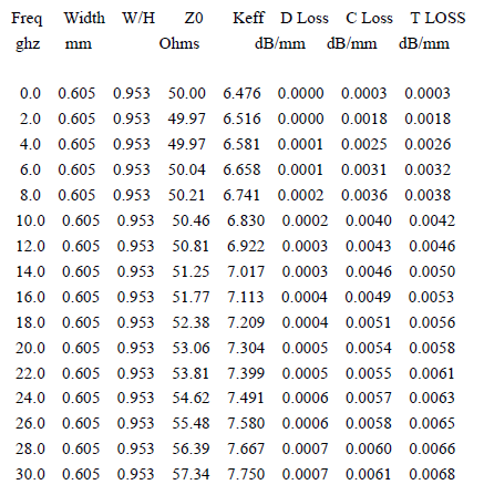
Using this sweep analysis, determine how the impedance and Keff change with frequency, and the change in dielectric loss (D Loss), conductor loss (C Loss) and the total loss (T Loss) vary with frequency. At 0 GHz, the results reproduce the synthesized impedance of 50 ohms, and this impedance then rises at higher frequencies.
To convert from electrical length to physical length, enter the electrical length and the frequency:
E: 45 degrees
Frequency: 10 GHz
Click Synthesis. Since the frequency is now set to 10 GHz, a new width is calculated to maintain an impedance of 50 ohms. The equivalent physical length is also computed:
W: 0.617 mm
P: 1.432 mm