
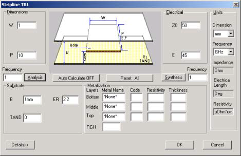
TRL Edge-Coupled Suspended Stripline Transmission Lines
|
Keyword |
Default |
Unit |
Description |
|
|
|
W |
Req (Phys) |
m |
Conductor width |
||
|
S |
Req (Phys) |
m |
Spacing between conductors |
||
|
P |
0 |
m |
Physical length of transmission line |
||
|
Z0 |
Req (Elec, Opt 1) |
ohm |
Impedance of the coupled lines |
||
|
K |
Req (Elec, Opt 1) |
dB |
Coupling coefficient (positive) |
||
|
Zo |
Req (Elec, Opt 2) |
ohm |
Odd-mode impedance of the coupled lines |
||
|
Ze |
Req (Elec, Opt 2) |
ohm |
Even-mode impedance of the coupled lines |
||
|
E |
0 |
deg |
Electrical length of the coupled lines |
||
|
Frequency |
100 MHz |
Hz |
Analysis frequency |
||
|
ER |
Required |
|
Relative dielectric constant |
||
|
H |
Req |
m |
Substrate thickness |
||
|
HL |
Req |
m |
Distance between bottom of substrate and ground |
||
|
HU |
Req |
m |
Cover height above substrate |
||
|
A |
inf. |
m |
Width between sidewalls |
||
|
TAND |
0 |
|
Dielectric loss tangent |
||
|
RGH |
0 |
m |
Rms surface roughness |
||
Synthesis and Analysis
Two options exist for synthesis of edge-coupled suspended substrate transmission lines:
— Specify impedance, Z0, and the coupling coefficient, K.
— Specify the even-mode impedance, Ze, and the odd-mode impedance, Zo.
- The substrate parameters H, HU, HL, A, and ER must be entered prior to clicking Synthesis. The width of the strips, W, and the spacing between them, S, is computed. Also, the alternate electrical option set is computed. For example, entering Z0 and K computes Ze and Zo.
- For analysis, the parameters W, HU, HL, and ER must be entered prior to clicking Analysis. The electrical properties, Z0, K, Zo, and Ze is computed. The frequency is used if entered; otherwise, 100 MHz is used in the calculation.
- Conversion from electrical length, E, to physical length, P, can be performed by entering values for E and Frequency. Click Synthesis to compute P. Similarly, to convert from physical length to electrical length, enter values for P and Frequency and click Analysis to compute E.
Dielectric Substrates
A dielectric substrate is defined by the parameters H, ER, and TAND. The substrate is assumed to be lossless unless TAND is specified and greater than zero.
Conductor Metalization
- The selection of the conductor is performed in the Metalization group. The conductor isn’t specified, in this case the conductor loss is zero and no thickness corrections are made to the propagation characteristics. Up to three conductors of different metal and different thickness can be selected.
- Metalization rms surface roughness, RGH, can be specified for additional conductor losses due to imperfect metal surfaces. RGH is specified in terms of rms variation from an ideal flat surface.
Sweep Options
Parameters that can be swept for edge-coupled suspended substrate lines are:
Frequency
Width, W
Spacing, S
The order shown is the order used to generate output data when multiple parameters are swept simultaneously. See the Sweep Entries topic for further information.
Limitations
Full-wave analysis is used; there are no limitations for practical dimensions.
Example
To select the edge-coupled suspended substrate medium, select TRL on the Product menu, select Stripline, and click CPL. Set the units to mm and GHz. Enter the following parameters to synthesize a 6-dB coupler at 10 GHz:
Impedance, Z0: 50 ohms
Coupling, K: 6 dB
Frequency: 10 GHz
Substrate thickness, H: 0.635 mm
Lower height, HL: 1.0 mm
Upper height, HU: 1.0 mm
Sidewall width, A: 10.0 mm
Dielectric constant, ER: 9.8
TAND 0.001
Metal: Cu 0.01 mm
Click Synthesis to determine the coupler’s parameters:
Width, W: 1.122 mm
Spacing, S: 0.112 mm
Odd-mode impedance, Zo: 28.8 ohms
Even-mode impedance, Ze: 86.7 ohms
Odd-mode Keff, KO: 4.54
Even-mode Keff, KE 2.11
To specify a 1/4 wavelength line, enter:
Electrical length, E: 90
Click Synthesis again to determine the corresponding physical length:
Physical length, P: 4.12 mm
A sweep analysis can be performed on W, S, or Frequency. To perform a sweep analysis on W, type 0.8,1.2,0.05 in the W field to specify a sweep from 0.8 mm to 1.2 mm in steps of 0.05 mm. Clicking Analysis then yields the following results:
Coupled Lines in Suspended Substrate Stripline
H = 0.635mm ER = 9.80 TAND = 0.00100 T/H = 0.0157
Freq S/H W/H ZE ZO KE KO C Loss D Loss T Loss
ghz Ohms Ohms (dB/mm ) (dB/mm ) (dB/mm )
10.0 0.176 1.260 101.4 31.0 2.283 4.815 0.0102 0.0025 0.0127
10.0 0.176 1.339 98.8 30.6 2.251 4.770 0.0099 0.0025 0.0123
10.0 0.176 1.417 96.3 30.2 2.222 4.726 0.0096 0.0024 0.0120
10.0 0.176 1.496 93.9 29.8 2.194 4.682 0.0093 0.0024 0.0117
10.0 0.176 1.575 91.6 29.5 2.168 4.638 0.0091 0.0024 0.0114
10.0 0.176 1.654 89.5 29.2 2.144 4.595 0.0088 0.0024 0.0112
10.0 0.176 1.732 87.5 28.9 2.122 4.553 0.0086 0.0023 0.0110
10.0 0.176 1.811 85.5 28.6 2.101 4.511 0.0084 0.0023 0.0107
10.0 0.176 1.890 83.7 28.4 2.082 4.469 0.0082 0.0023 0.0105