
Single-Ended TDR
The schematics for all three TDR demonstrations are in one project in the Examples directory.
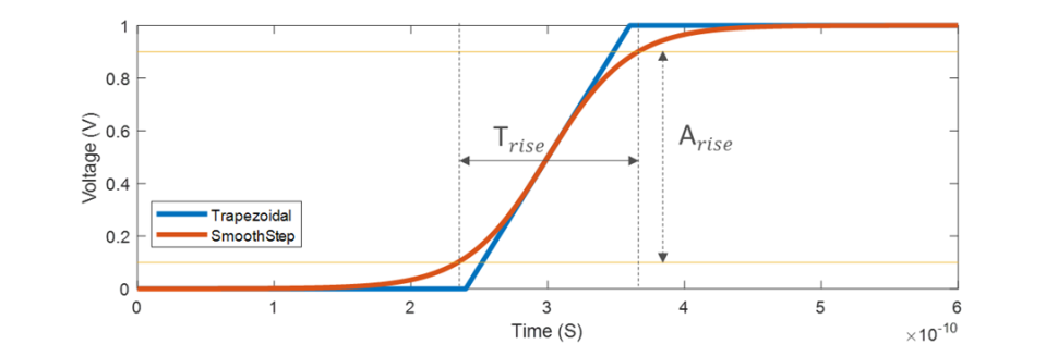
The following example is for a Single-Ended Time Domain Reflectometer using a Trapezoidal waveform. The TDR probe also provides the option for a Smooth Step waveform, which provides a more realistic step input and allows control of the rise interval. Step 4 is optional; it demonstrates how to choose between the Trapezoidal and SmoothStep waveform for analysis.
Open the TDR Schematic project from its file in the Examples directory.
- From the File menu, select Open Examples to open a file explorer window.
- Select Circuit > Signal Integrity, scroll to find and select TDR_Example.aedt, click Open.
In the Project Tree, Expand the TDR_Example icon and the 1_Single Ended icon. The single-ended TDR schematic appears in the design window:

The single-ended TDR consists of a unit pulse source, an internal impedance of Z0 ohm, a reference length of transmission line (Z0-ohm impedance, 0.5ns delay), and two voltage probes, Vexcited_pos for the step voltage and Vdetected_pos for the reflected voltage. (Z0 is the TDR component parameter.)
The Device Under Test (DUT) is a series of transmission lines and discrete passives to represent the typical TDR problem of finding where impedance changes in a line.
In sequence, the DUT elements are:
- Transmission line, 50-ohm impedance, 1 ns delay
- Shunt capacitor, 1 pf
- Transmission line, 50-ohm impedance, 3 ns delay
- Transmission line, 55-ohm impedance, 5 ns delay
- Series inductor, 5 nH
- Transmission line, 25-ohm impedance, 2 ns delay
- Series resistor, 1 gigohm
- Terminating ground
- The Examples directory is write-protected. Use File > Save As to save the example project to a directory where you have write permission. A Handle Project Directory Files window opens showing you the supporting model files that is copied along with the project. Click OK.
- (Optional) Choose between Trapezoidal and SmoothStep.
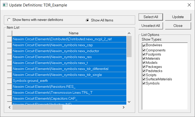
- Click Tools > Project Tools > Update Definitions.
- In the Update Definitions dialog, select Show All Items, Select All, then click Update . Close the dialog once updates are successful.
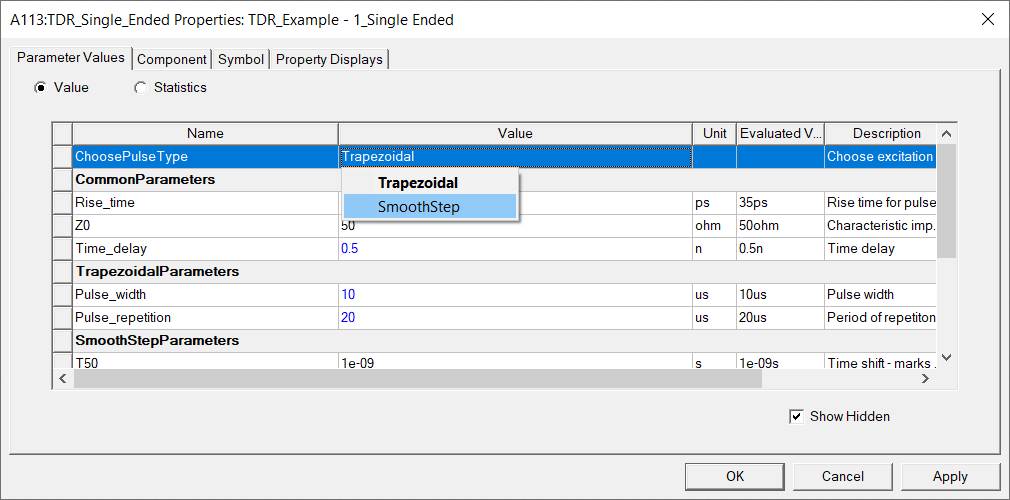
Right-click the TDR model symbol and click Properties to open the properties dialog.
Click the Value field for ChoosePulseType to view the two options. Select SmoothStep, click Apply, then OK to close the dialog.
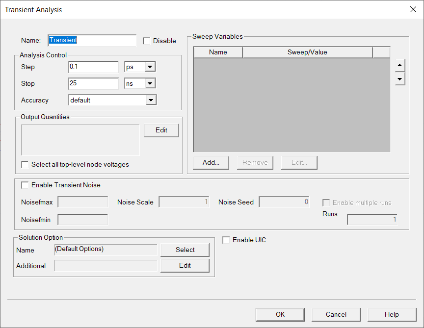
- In the Project Tree, expand the Analysis icon and double-click
on Transient to view the Transient Analysis setup. Click OK.
- In the Project Tree, right- click Transient and select Analyze. The analysis runs to completion.
- Expand the Reports icon and right-click on the Zload report setup. Select Modify Report to open the Report Setup.
- Click New Report to
generate the report:
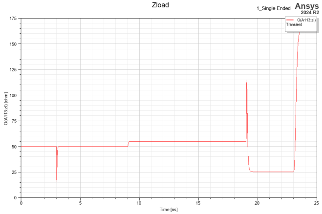
The TDR analysis allows us to identify each of the components of the DUT by their timing and behavior. Using the Trapezoidal waveform, the reflection timings are expected at 2*(Total Delay):
- At 3ns, the impedance drops to indicate the presence of the capacitor. The 3ns delay is the TDR internal delay (0.5ns) plus the first transmission line delay (1ns), times two for the reflection. Both transmission lines are at 50 ohms.
- At 9ns, the impedance increases to 55 ohm at the beginning of the 55-ohm line segment. 9ns=2(0.5+1.0+3.0).
- At 19ns, the impedance jumps to indicate the presence of the inductor, then immediately drops to25 ohm for the resistor. 19ns=2((0.5+1.0+3.0+5.0).
- At 23ns, the impedance goes to infinity at the
high final resistor.
23ns=2(0.5+1.0+3.0+5.0+2.0).

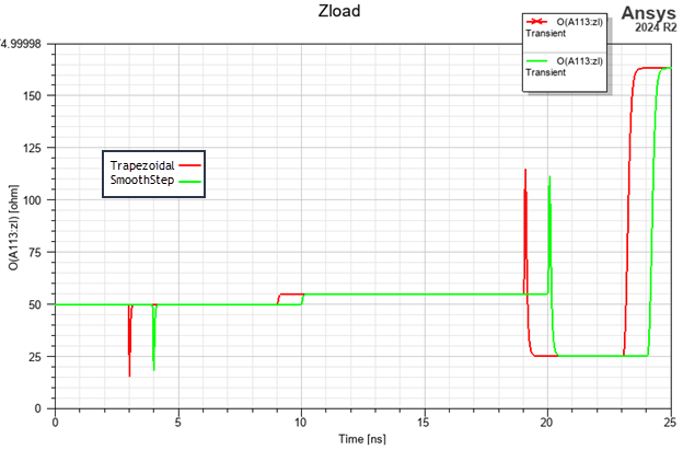
For a SmoothStep waveform, the reflection timings are expected at T50 + 2*(Total Delay):
- At 4ns, the impedance drops to indicate the presence of the capacitor. The 4ns delay is the TDR internal delay (0.5ns) plus the first transmission line delay (1ns), times two for the reflection, plus 1 ns for the T50 parameter. Both transmission lines are at 50 ohms.
- At 10ns, the impedance increases to 55 ohm at the beginning of the 55-ohm line segment. 10ns= 1 + 2(0.5+1.0+3.0).
- At 20ns, the impedance jumps to indicate the presence of the inductor, then immediately drops to 25 ohm for the resistor. 20ns= 1 + 2((0.5+1.0+3.0+5.0).
- At 24ns, the impedance goes to infinity at the
high final resistor.
24ns= 1 + 2(0.5+1.0+3.0+5.0+2.0).