
Plot I-V Curves of Active Components
A current-voltage characteristic, or I-V curve, is the relationship between an electric current and its corresponding voltage. The electric current can be a circuit, device, or material. An I-V curve is typically represented as a chart or graph , then a plot of the current-voltage relationship can be traced. This is referred to as the I-V characteristic of the element. When the I-V characteristic of the element is in the load subcircuit, it is plotted via standard labeling. A resistor satisfies Ohm's law, so the I-V characteristic of the element passes through the origin and possesses slope.
DC-IV plots are supported for the following devices:
To generate a plot that displays I-V curves:
- Open a project that contains one of the devices listed above; for example, BJT_inverter.aedt.
- In the Schematic Editor, right-click the BJT device and select Display IV Curves. A schematic plot that shows I-V curves is generated and displayed.
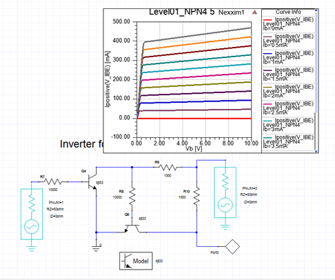
A corresponding I-V solution for the device is created beneath Analysis in the Project Manager window. - To modify curves, select the I-V solution in the Project Manager window to open the Sweep Definition window.
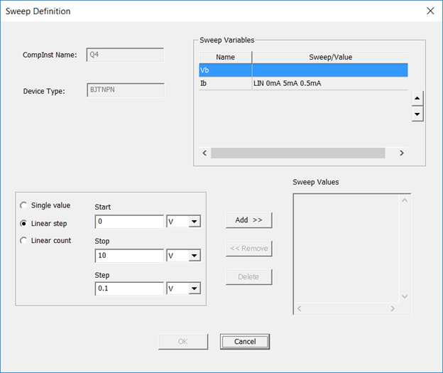
The Sweep Values pane displays the values of the variable selected in the Sweep Variables pane.
— To add a sweep value: Select Start, Stop, and Step values at lower-left, then click Add >>.
— To edit a sweep value: Select a sweep on the Sweep Values list, then click << Remove.
Then modify the Start, Stop, and Step values, then click Add.
— To delete a sweep value: Select a sweep on the Sweep Values list, then click Delete.
This deletes the I-V solution and the corresponding plot.
After making modifications, when you click OK the I-V curves are automatically updated.