
Thermal Model Identification
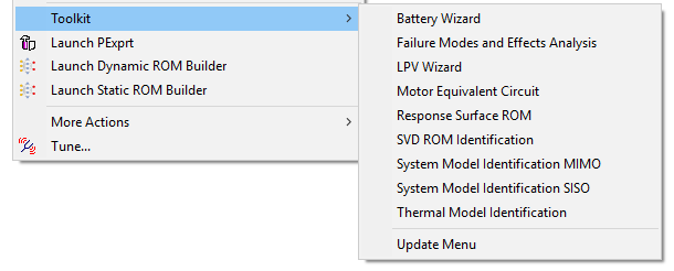
The Thermal Model Identification option under Twin Builder > Toolkit provides access to accurate reduced order models (ROMs) that you can bring into Twin Builder for system level analysis and simulation.
Each ROM is built from the accurate simulation results (step responses/frequency responses) from Finite Element Analysis (FEA) tools with Linear Time Invariant (LTI) vector fitting techniques.
Access detailed help files and demo examples under [installation directory]\Win64\Examples\Twin Builder\Applications\Thermal Model Identification\.
Click Help on the Thermal Model Identification dialog box to view input information.
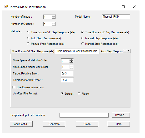
- In the Response/Input File Location box, browse to the example you want to use and select the folder containing the resource data. Click Load Config to restore the existing parameter information on the toolkit interface.
- In the Number of Inputs box, enter the number of independent heat sources.
- In the Number of Outputs box, enter the number of measurement points.
- For the Model Name, enter the name for the model within Twin Builder. Do not use spaces, hyphens, or other special characters.
- Select a method from the Methods options. You can edit parameters on the corresponding tab.
| Method | Parameter | Description |
|---|---|---|
| Time Domain VF Step Response (ele) | State Space Model Min Order | Minimum order used. A higher order gives more accurate results, but takes longer to simulate. If 0 is used, then a contribution might be ignored based on the Tolerance for 0th Order specified. |
| State Space Model Max Order | 40th order is set to be the maximum. For thermal problems, an 8th order should work well for most applications. | |
| Target Relative Error | This is used to determine the order. | |
| Tolerance for 0th Order | This is used to ignore certain contributions if its value is less than the tolerance multiplied by the largest contribution. | |
| Use Conservative Pins | This option allows for conservative pins to be used for the pairs of inputs/outputs specified in the Input_ConPins.txt file. | |
| NonZero StepRes Slope | If your ROM is not expected to reach a steady state, select Calculate so the system will calculate the slope based on data in the step response files, or Provide if the slope is provided in a separate file. Select No if the step response is expected to reach a steady state. | |
| StepRes File Format | Choose the file format of your step response file. Default format includes a separate file for each input/output combination. Fluent format includes a separate file for each input; all outputs for a given input are included in a single file. | |
| Time Domain VF Any Response (ele) | State Space Model Min Order | Minimum order used. A higher order gives more accurate results, but takes longer to simulate. If 0 is used, then a contribution might be ignored based on the Tolerance for 0th Order specified. |
| State Space Model Max Order | 40th order is set to be the maximum. For thermal problems, an 8th order should work well for most applications. | |
| Target Relative Error | This is used to determine the order. | |
| Tolerance for 0th Order | This is used to ignore certain contributions if its value is less than the tolerance multiplied by the largest contribution. | |
| Use Conservative Pins | This option allows for conservative pins to be used for the pairs of inputs/outputs specified in the Input_ConPins.txt file. | |
| Any File Format | Choose the file format of your response file of any type of response than step response. Default format includes a separate file for each input/output combination. Fluent format includes a separate file for each input; all outputs for a given input are included in a single file. | |
| Auto Step Response (ele) | State Space Model Min Order | Minimum order used. A higher order gives more accurate results, but takes longer to simulate. If 0 is used, then a contribution might be ignored based on the Tolerance for 0th Order specified. |
| State Space Model Max Order | 40th order is set to be the maximum. For thermal problems, an 8th order should work well for most applications. | |
| Target Relative Error | This is used to determine the order. | |
| Tolerance for 0th Order | This is used to ignore certain contributions if its value is less than the tolerance multiplied by the largest contribution. | |
| Sampling dt Factor | This is used to increase or decrease the sampling dt, which is determined automatically. | |
| Keep Parameter Files | This allows the program to write out all parameters used into files. These files are useful for the manual step response (ele) method. | |
| Use Conservative Pins | This option allows for conservative pins to be used for the pairs of inputs/outputs specified in the Input_ConPins.txt file. | |
| Manual Step Response (ele) |
When this method is used, all parameters are from files, and they are not shown in the panel. There are a few additional parameters besides the ones used for other methods. When calculating the Fourier transform, FFT is the default method. For some cases, FFT becomes too time consuming. You can also use a numerical method to calculate the Fourier transform, called NFT. The flag for this is F for FFT and N for the NFT method. When using NFT, you can choose linear or quadratic interpolation. The flag for this is l for linear and q for quadratic. When using FFT, you must choose the maximum frequency for fitting along with the number of points used to represent the FT before vector fitting. Another parameter is the minimum number of iterations during vector fitting. |
|
| Manual Step Response (col) | State Space Model Order | The order is used for column fitting. 40th order is set to be the maximum. For thermal problems, a 15th order should be enough for most applications. |
| Sampling Period | This the sampling period used to sample the step responses before FFT is performed. | |
| VF Number of Points | The number of frequency points for the lower frequency portion of the FFT for vector fitting. This portion becomes the sampled Fourier transform of the original system. Note that the entire FFT is not the sampled Fourier transform. | |
| Padding Factor | Add additional zero padding before FFT. (It is not critical to know the zero padding. Using 0 or 1 should be fine.) | |
| Interpolation Method | When calculating impulse response from step response, an interpolation is used first followed by derivative. Cubic Spline is more accurate, but the linear method is faster. For cases with many data points, it might be sufficient to use the Linear method without loss of accuracy. Interpolation is also needed when smoothing the given impulse responses. | |
| Coarsen Sampled Freq. Responses by a Factor of | The sampled frequency responses may have too many data points for vector fitting. You could reduce the number of data points before performing vector fitting. If 2 is used, only half of the data points are used. | |
| Use Conservative Pins | This option allows for conservative pins to be used for the pairs of inputs/outputs specified in the Input_ConPins.txt file. | |
- Click Generate to create the model, which is added under Project Components in the Components Libraries dialog box. You are notified that an LTI ROM was generated and can be loaded into Twin Builder for calculation.
- Click Close.