
Test Circuit Conditions

Choose the Test Circuit Conditions parameter settings for the IGBT type being characterized:
- Basic Dynamic or Advanced Dynamic IGBT Half-Bridge Test Circuit Conditions
- Average IGBT Half-Bridge Test Circuit Conditions
- Power MOSFET Test Circuit Conditions
Half-Bridge Test Circuit Condition for a Basic Dynamic or Advanced Dynamic IGBT
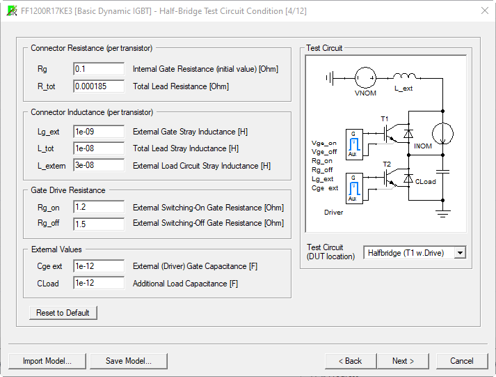
See Vendor-Specific Guidelines for Basic Dynamic IGBT Half-Bridge Test Circuit Condition below when making the following settings.
|
Internal Gate Resistance Rg (Ohm) |
Listed in table of characteristics in datasheet. Default value is 0.2. |
|
Total Lead Resistance R_tot (Ohm) |
R_tot is the lead resistance per switch of the IGBTs. This value is used to calculate RE and RC in the parameterized device generated by the device characterization wizard. If the datasheet provides the resistance for a half-bridge module, R_tot will be half of the value given on the datasheet. Unless specified by the manufacturer, this value should remain at the default value of 0. Contact the device manufacturer to get a measured value for this parameter if desired. NOTE: This value must be less than 0.250/Inom. |
|
External Gate Stray Inductance Lg_ext (H) |
This value should remain at the default value unless specified in the manufacturer’s specification. Default value is 0. |
|
Total Lead Stray Inductance L_tot (H) |
L_tot is the lead stray inductance per switch. This is used to calculate LE, LAUX and LC in the parameterized device generated by the device characterization wizard. If the datasheet provides the stray inductance for a half-bridge module, L_tot will be half of the value given on the datasheet. The manufacture may provide a value for L_tot in the test conditions section of the switching characteristics parameters. If no value is supplied, leave the default value to prevent numerical instability. Default value is 0. Note: Some manufacturers list a value for L which is generally the Load Inductance used for the test and should not be interpreted as L_tot. |
|
Sum of External Load Path Stray Inductance L_extern (H) |
L_extern is the sum of the external load path stray inductance. This inductance is part of the half bridge circuit, which is used to determine the switching energies and times. This value will be fit for by the dynamic characterization tool, but it is not a part of the parameterized device generated by the parameterization wizard. The value entered here is used as a starting point for the fit. Unless specified in the manufacturer’s specification, the inductance value should remain at the default settings. This parameter may be specified when multiple devices are packaged in a module. Default value is 2e-009. |
|
Switching-On Gate Resistance Rg_on (Ohm) |
This parameter will generally be listed in the test conditions section of the on-switching characteristics as Rg. Default value is 0.001. |
|
Switching-Off Gate Resistance Rg_off (Ohm) |
This parameter is usually listed in the test conditions section of the off-switching characteristics as Rg. Unless otherwise specified in the manufacturer’s specification, set this parameter to the same value used for Rg_on. Default value is 0.001. |
|
External Gate Capacity Cge ext (F) |
This value should remain at the default value unless specified in the manufacturer’s specification. Default value is 0. |
Select the Use default values check box to apply the default values to the device being characterized.
When finished, click Next to continue characterizing the device. See (Transfer Characteristics).
Vendor-Specific Guidelines for Basic Dynamic IGBT Half-Bridge Test Circuit Condition
Refer to the follow vendor-specific guidelines when setting values:
|
Vendor |
Guidelines |
|
ABB |
R_tot is given by R_cc_ee or half of R_cc_ee in the datasheet, depending if the value is per switch or for the whole module. L_tot is given by half of Lsce in the datasheet, depending if the value is per switch or for the whole module. L_extern can be listed as Ls in the measurement conditions of Eon and Eoff. Rg_on and Rg_off are usually listed as RG in the measurement conditions of the switching times and energies. Cge_ext is usually not listed. If not listed, 1pF is a good approximation. |
|
Hitachi |
R_tot is usually not listed in the datasheet, using 0 is a good approximation, as the DC characterization will adapt. L_tot is given by Lsce or half of Lsce in the datasheet, depending if the value is per switch or for the whole module. L_extern can be listed as L in the measurement conditions of Eon and Eoff. Rg_on and Rg_off are usually listed as RG in the measurement conditions of the switching times and energies. Cge_ext is usually listed as Cge in the measurement conditions of the switching times and energies. If not listed, 1pF is a good approximation. |
|
Infineon |
R_tot is given by R_cc_ee or half of R_cc_ee in the datasheet, depending if the value is per switch or for the whole module. L_tot is given by Lsce or half of Lsce in the datasheet, depending if the value is per switch or for the whole module. L_extern can be reported as Ls in the measurement conditions of Eon and Eoff. Rg_on and Rg_off are usually reported as RG in the measurement conditions of the switching times and energies. Cge_ext is usually not listed by Infineon. If not listed, 1 pF is a good approximation. |
|
IXYS |
R_tot is generally not supplied; a default value of 0 is then appropriate. L_tot is generally not supplied; a default value of 0 H is then appropriate. L_extern is generally not supplied; a default value of 30 nH is then appropriate. Rg_on and Rg_off are usually given as RG in the measurement conditions of the switching times and energies. Cge_ext is usually not listed. If not listed, 1pF is a good approximation. |
|
Mitsubishi |
R_tot is given by Rlead or half of Rlead in the datasheet, depending if the value is per switch or for the whole module. L_tot is generally not supplied; a default value of 0 H is then appropriate. L_extern is generally not supplied; a default value of 30 nH is then appropriate. Rg_on and Rg_off are usually listed as RG in the measurement conditions of the switching times and energies. Cge_ext is usually not listed. If not listed, 1pF is a good approximation. |
|
Semikron |
R_tot is given by R_cc_ee or half of R_cc_ee in the datasheet, depending if the value is per switch or for the whole module. L_tot is given by Lsce or half of Lsce in the datasheet, depending if the value is per switch or for the whole module. L_extern can be listed as Ls in the measurement conditions of Eon and Eoff. Rg_on and Rg_off are usually listed as RG in the measurement conditions of the switching times and energies. Cge_ext is usually not listed. If not listed, 1pF is a good approximation. |
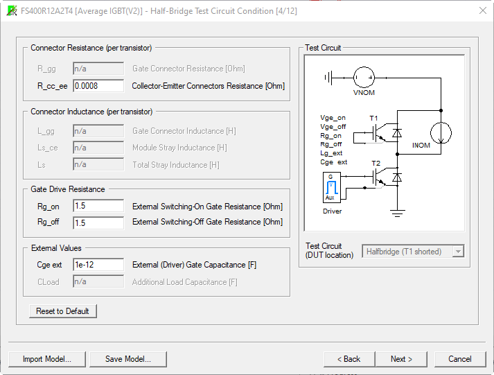
Half-Bridge Test Circuit Condition for an Average IGBT
|
Gate Connector Resistance R_gg (Ohm) |
Not applicable. |
|
Collector-Emitter Connectors Resistance R_cc_ee (Ohm) |
Unless specified by the manufacturer, this value should remain at the default value of 0. Contact the device manufacturer to get a measured value for this parameter if desired. Note: This value must be less than 0.250/Inom. |
|
Gate Connector Inductance L_gg (H) |
Not applicable. |
|
Total Stray Inductance Ls (H) |
Not applicable. |
|
Module Stray Inductance Ls_ce (H) |
Not applicable. |
|
Switching-On Gate Resistance Rg_on (Ohm) |
This parameter will generally be listed in the test conditions section of the switching characteristics as Rg. Default value is 1. |
|
Switching-Off Gate Resistance Rg_off (Ohm) |
Unless otherwise specified in the manufacturer’s specification, set this parameter to the same value used for Rg_on. Default value is 1. |
|
External Gate Capacity Cge_ext (F) |
This value should remain at the default value of 0 unless specified in the manufacturer’s specification. |
Test Circuit Condition for a Power MOSFET
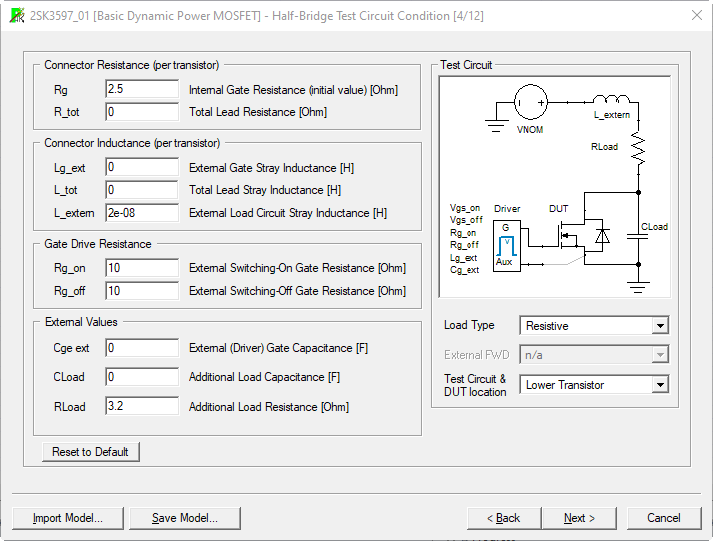
| Internal Gate Resistance Rg (Ohm) | Listed in table of characteristics in datasheet. Default value is 0.2. |
| Total Lead Resistance R_tot (Ohm) | R_tot is the lead resistance per switch of the MOSFET. This value is used to calculate RE and RC in the parameterized device generated by the device characterization wizard. If the datasheet provides the resistance for a half-bridge module, R_tot will be half of the value given on the datasheet. |
| External Gate Stray Inductance Lg_ext (H) | This value should remain at the default value unless specified in the manufacturer’s specification. Default value is 0. |
| Total Lead Stray Inductance L_tot (H) |
L_tot is the lead stray inductance per switch. This is used to calculate LE, LAUX and LC in the parameterized device generated by the device characterization wizard. If the datasheet provides the stray inductance for a half-bridge module, L_ tot will be half of the value given on the datasheet. The manufacturer may provide a value for L_tot in the test conditions section of the switching characteristics parameters. If no value is supplied, leave the default value to prevent numerical instability. Default value is 0. Note: Some manufacturers list a value for L which is generally the Load Inductance used for the test and should not be interpreted as L_tot. |
| Sum of External Load Path Stray Inductance L_extern (H) | L_extern is the sum of the external load path stray inductance. This inductance is part of the half bridge circuit, which is used to determine the switching energies and times. This value will be fit for by the dynamic characterization tool, but it is not a part of the parameterized device generated by the parameterization wizard. The value entered here is used as a starting point for the fit. Unless specified in the manufacturer’s specification, the inductance value should remain at the default settings. This parameter may be specified when multiple devices are packaged in a module. Default value is 2e-009. |
| Switching- On Gate Resistance Rg_on (Ohm) | This parameter will generally be listed in the test conditions section of the on- switching characteristics as Rg. Default value is 0.001. |
| Switching- Off Gate Resistance | This parameter is usually listed in the test conditions section of the off-switching characteristics as Rg. |
| External Gate Capacity Cge ext (F) | This value should remain at the default value unless specified in the manufacturer’s specification. Default value is 0. |
MOSFET devices are usually tested in a Half-Bridge circuit where the DUT is in the lower location and the upper device is replaced by a diode or a resistor. However, you can choose other configurations, like the DUT in the upper location or a real Half-Bridge circuit. Depending on the configuration some of the other settings are available or not. The test circuit picture adjusts according to the settings of the test circuit type, load type, and external FWD type and shows a simplified picture of the test circuit.
| Test circuit & DUT location | Available settings are Half-Bridge, Upper Transistor, and Lower Transistor. |
| Load Type | Can be set when the type of test circuit is not set to Half-Bridge. Available settings are resistive or inductive. |
| External FWD | Type of the external freewheeling diode when the type of the test circuit is not set to Half-Bridge and the load type is inductive. The FWD can be static, dynamic, or dynamic with reverse recovery. |
| RLoad | Value of the load resistance if the load type is resistive. |
Select the Use default values check box to apply the default values to the device being characterized.
When finished, click Next to continue characterizing the device. See Transfer Characteristics.