Creating a Sample Pin Group, Step 4: Create a Port
Create a port between the two pin groups:
- From the Modeling workspace, select the two pin groups.
- Click Tools > Generate Circuit Element on Components.
- From the Circuit Element Positive Terminal area, select U1_NET_2_Group as the positive terminal.
- From the Circuit Element Reference Terminal area, select U1_NET_1_Group as the negative terminal.
- From the Circuit Element Type area, ensure that Port is selected.
- Click Create.
- Leave the default Name and Reference Impedance.
- Click OK to exit the Port Properties window.
- Click OK to exit the Circuit Element Generation Dialog.
The Circuit Element Generation Dialog appears.

Note: If individual terminals need to be selected, the pin group must be deleted.
Note: If individual terminals need to be selected, the pin group must be deleted.
The Port Properties window appears.

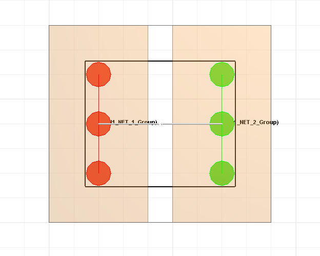
The port appears in the Modeling workspace, with positive terminals highlighted in red and negative terminals highlighted in green.
Click the port to display pin group names.