
PinToPin Export Automation
The PinToPin utility can quickly extract HFSS or SIwave models for specified nets of package and PCB geometries. It establishes a repeatable process for robust geometry extraction, port configuration, and passive model assignment. Process execution can be done via the user interface (Windows only) or in non-graphical mode (Windows or Linux).
Launching PinToPin Utility
To launch the PinToPin utility in non-graphical mode, type:
- PinToPinSetup <workingDir> <path to XML control file> <path to appropriate EDB or XML output>
To launch the PinToPin utility from within SIwave:
- Click Tools. From the External Tools area, click PinToPin Setup
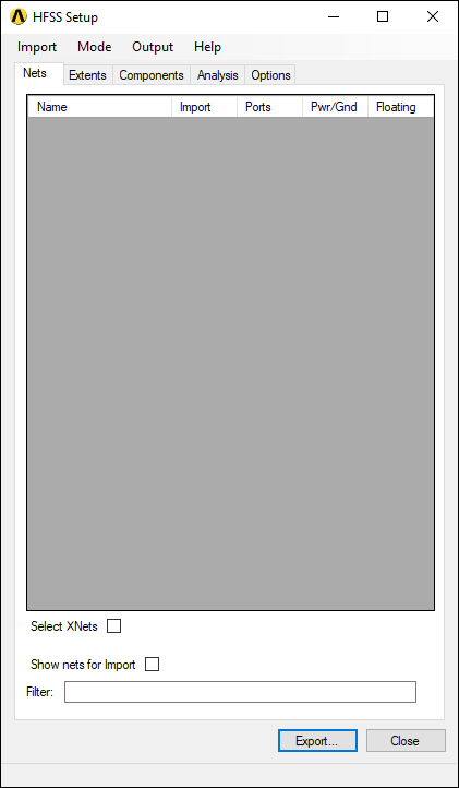
The PinToPin utility launches in a window labeled HFSS Setup.
Importing a File
To import a file into PinToPin utility, click Import and select a file type.
Supported file types are:
- Cadence Allegro/APD/SIP (*.brd, *.mcm, *.sip)
- ODB++ (*.tgz)
- IPC2581 (*.xml, *.cvg)
- Ansys EDB (*.def)
- XML configuration file (*.xml)
For Cadence, ODB++, and IPC2581 files, the AnsTranslator window will appear and alert you of translation progress:
![]()
It will then let you know whether translation has succeeded or failed.
![]()
![]()
Once the file has been loaded, the window name changes to the file name.
Selecting a Simulation Mode
Click Mode and select either HFSS or SIwave.
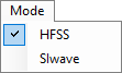
The contents of the Analysis tab change based on this selection, and the Extents tab appears only for HFSS mode.
Changing PinToPin Settings
The PinToPin utility window contains up to five tabs:
- Nets – allows you to select nets for import, and to quickly denote ports, power/ground nets, and floating nets. You can also filter the nets using regular expressions.
- Extents (HFSS mode only) – allows you to specify cutout, airbox, and dielectrics settings.
- Components – allows you to change component part types, and to set model, solderball, die, and port properties.
- Analysis – allows you to set simulation and frequency sweep options.
- Options – allows you to alter the port naming convention or bondwire definitions.
For more information about these options, see PinToPin Settings.
To configure default settings, generate a PinToPinSetup.xml configuration file and place it in the same folder as PinToPinSetup.exe.
Exporting a File
Click Output and select one of the following:
- HFSS 3D Layout – *.aedb folder that can be imported into either Ansys Electronics Desktop or SIwave.
- XML – *.xml file that can be used in subsequent calls to PinToPin. This is a good way to save a configuration or create a template that can be called repeatedly to create multiple models from the same file.
Click Export to generate the selected file type.
Troubleshooting PinToPin Utility
PinToPinSetup writes log files to the working directory. These log files may provide useful information about warnings or errors encountered during model generation.