
Calculating Derived Field Quantities Using Named Expressions
The Named Expressions panel displays expressions that can be included in register definitions by name. You can add additional expressions to the Named expression list by creating the expression in the register display area and then clicking the Add button. This lets you add to the Named expression library.
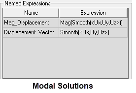
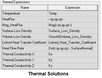
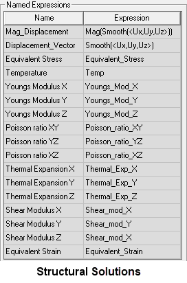
Predefined named expressions for Mechanical designs are shown below for each solution type:
Click on a named expression to select it. When a named expression has been selected, the Copy to Stack button is activated. Click Copy to Stack to push the expression on the top of the stack.
When
|
Expression Name |
Expression Definition |
|
Mag_Displacement
|
Mag(Smooth(<Ux,Uy,Uz>)): The resultant magnitude of the displacement vectors, which represent the deformed shape of the selected vibration mode for Modal solutions and the actual structural deformation for Structural solutions. Note:
For Modal solutions, the displacement results are not scaled to any specific structural excitation but are arbitrary. Only the relative displacements throughout the model are meaningful in that they demonstrate the vibration mode shape. The absolute displacement magnitudes are not meaningful for Modal solutions and may in fact be well out of proportion with the physical size of the structure. |
|
Displacement_Vector |
Smooth(<Ux,Uy,Uz>): A vector representation of the preceding displacement expression. For Modal solutions, see the preceding note for Mag_Displacement, which also applies to this vector expression. |
|
Note:
If you create and run the Modal Toolkit Example, four additional expressions will be added to the Named Expressions panel: the normalized displacement (≤ 1 length unit) and the X, Y, and Z components of the displacement vector. |
|
|
Temperature
|
Temp: The temperature at each calculation point throughout the model. This result is useful for verifying that temperatures have been properly mapped to the model when importing thermal conditions from a separate source solution. |
|
HeatFlux
|
<qx,qy,qz>: The heat flow rate vector defined on a power per unit area basis. |
|
Mag_HeatFlux
|
Mag(<qx,qy,qz>): The magnitude of the HeatFlux vector. |
|
Surface Loss Density
|
Surface_Loss_Density: This quantity concerns thermal excitations (EM Losses) imported from the surfaces in another design. The electromagnetic losses are due to inherent inefficiencies in the materials, and these become a source of heat in the thermal solution. |
|
Volume Loss Density
|
Smooth(Volume_Loss_Density): This quantity concerns thermal excitations (EM Losses) imported from the volumes in another design. The electromagnetic losses are due to inherent inefficiencies in the materials, and these become a source of heat in the thermal solution. |
|
Linked Heat Transfer Coefficient
|
Linked_Heat_Transfer_Coefficient: The imported convection Film Coefficients when you have choosen the Non-Uniform option and have set up a link to an Icepak source solution. |
|
Heat Flow Rate
|
Dot(<qx,qy,qz>, SurfaceNormal): The surface-normal component of heat flux used to approximate total heat flow rates at specified faces by integration. A face list is required for the integration faces to be selectable within the Fields Calculator. Note that there are effects at the edges of faces that skew the total integrated heat flow values when this method is employed. As such heat flow may appear to be out of equilibrium. More accurate Heat Flow Rate results can be obtained by creating a Fields Summary. Additionally, you can directly select boundaries, such as Contact and Convection assignments, in the Create Fields Summary dialog box. That is, you need not create face lists to determine the total heat flow rates at boundaries when creating a Fields Summary. |
|
Thermal Conductivity X, Y, and Z
|
Kx, Ky, and Kz: The thermal conductivity in the X, Y, and Z directions, respectively, for layout component materials. (See Note [1] at the bottom of this table.) |
|
Note:
If you create and run the Thermal Toolkit Example, three additional expressions will be added to the Named Expressions panel: specifically, the global maximum, mean, and minimum temperature results (Global_Max_Temp, Global_Mean_Temp, and Global_Min_Temp). Each of these named expressions reports a single value from the set of all object volumes. |
|
|
Equivalent Stress
|
Equivalent_Stress: The von Mises equivalent stress at each calculation point throughout the model. The equivalent stress result combines the effects of the six individual stress tensors or three principal stresses. It is typically compared to the material's yield strength for ductile metals. For brittle materials, this stress may be compared to the ultimate tensile strength. |
|
Young's Modulus X, Y, and Z
|
Youngs_Mod_X, Youngs_Mod_Y, and Youngs_Mod_Z: The modulus of elasticity in the X, Y, and Z directions, respectively, for layout component materials. (See Note [1] at the bottom of this table.) |
|
Poisson's Ratio XY, YZ, and XZ
|
Poisson_ratio_XY, Poisson_ratio_YZ, and Poisson_ratio_XZ: These ratios quantify how the cross-section of a material sample changes as it is strained in the perpendicular direction. Three values are available, each being the negative of the ratio of transverse strain and axial strain resulting from an applied axial load. (See Note [1] at the bottom of this table.) |
|
Thermal Expansion X, Y, and Z
|
Thermal_Exp_X, Thermal_Exp_Y, and Thermal_Exp_Z: The coefficient of thermal expansion in the X, Y, and Z directions, respectively, for layout component materials. (See Note [1] at the bottom of this table.) |
|
Shear Modulus X, Y, and Z
|
Shear_mod_X, Shear_mod_Y, and Shear_mod_Z: Shear Modulus is also know as the modulus of rigidity, as it is a measure of the rigidity of a material. Specifically, it is the ratio of the shear stress and shear strain. (See Note [1] at the bottom of this table.) |
|
Equivalent Strain
|
Equivalent_Strain: The von Mises equivalent strain at each calculation point throughout the model. The equivalent strain result is calculated from the six strain tensor values and the effective Poisson's ratio (ν'), which equals the specified Poisson's ratio for isotropic materials undergoing elastic strain. Material strain is a dimensionless quantity though typically expressed in units of length/length. |
|
Note:
[1] – Directional results are applicable to designs that include trace mapping (that is, indirect representation of metals by locally altering dielectric material properties of the layout components). Properities are mapped to individual elements comprising the mesh. The resultant values can vary by direction even though the constituent material properties are isotropic. |
|