Frictionless Support
A frictionless support constrains faces from translating in the direction normal to the selected face or faces (both the positive and negative normal vector directions are constrained). You can use it, for example, to model an area of sliding contact between an object of interest and the floor, table, or machine that it rests on.
You can assign Frictionless Support boundaries to only the following entity type:
- Faces of solid objects
The faces to which you apply a Frictionless Support may be of any shape (flat, cylindrical, spherical, conical, or having irregular curvature). The normal direction, and thus the constraint direction, is evaluated separately at each node along the faces where the support is applied. Therefore, the direction of constraint will only be constant for a flat face or multiple parallel flat faces.
For curved faces, the constraint direction is estimated by averaging the normal vectors of the element faces that meet at each node. Therefore, the constraint direction is mesh-sensitive. For the best results, apply local mesh refinement to curved faces receiving a Frictionless Support boundary. The finer the elements, the smaller the angular differences between adjacent element faces and the greater the constraint direction accuracy.
How to Assign a Frictionless Support Boundary:
- Using the Face selection mode, select one or more solid object faces.
- Use one of the following three methods of accessing the Frictionless Support dialog box:
- Right-click in the Modeler window and choose Assign Boundary > Frictionless Support from the shortcut menu.
- Right-click Boundary in the Project Manager and choose Assign > Frictionless Support.
- From the menu bar, click Mechanical > Boundaries > Assign > Frictionless Support.
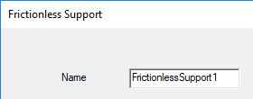
- Optionally, change the Name of the boundary. (The default name is FrictionlessSupportx, where x is a number incremented for each fixed support you add.)
- Click OK.
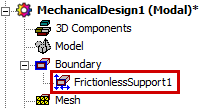
The frictionless support appears under Boundary in the Project Manager: