
Cylindrical Support
A Cylindrical Support prevents the faces to which it is applied from translating in any combination of the following three directions:
- Radial
- Axial
- Tangential
You can assign a Cylindrical Support to only the following entity type:
- Cylindrical Faces of solid objects.
The faces can be full or partial cylinders and can be the outside diameter face of a cylinder or the inside diameter face of a hole or hollow cylinder. Valid faces for a cylindrical support boundary are pictured below (highlighted in magenta):
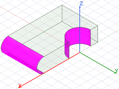
The radial and tangential directions are evaluated separately at each node along the faces where the support is applied. For each separate cylindrical face, the axial (or thrust) direction is constant because it corresponds to the cylinder's axis at every point on the face.
The radial constraint direction of the cylindrical face is estimated by averaging the normal vectors of the element faces that meet at each node. The tangential direction is at a right-angle to the radial and axial directions. Therefore, the radial and tangential constraint directions are mesh-sensitive. For the best results, apply local mesh refinement to faces receiving a Cylindrical Support boundary. The finer the elements, the smaller the angular differences between adjacent element faces and the greater the constraint direction accuracy.
By default, all three directions are initially Fixed when you start to apply a Cylindrical Support boundary. Therefore, the default boundary definition is equivalent to a Fixed Support boundary. To distinguish the behavior of the boundary from a fixed support, and to represent typical cylindrical support behavior, change the setting for one or two directions from Fixed to Free. For example, to represent a bearing support that prevents radial and axial translation of a shaft but permits tangential motion (that is, shaft rotation), change the Tangential setting to Free.
You can change the boundary defaults to suit your most commonly used setup.
How to Assign a Cylindrical Support Boundary:
- Using the Face selection mode, select one or more cylindrical faces of solid objects.
- Use one of the following three methods of accessing the Cylindrical Support dialog box:
- Right-click in the Modeler window and choose Assign Boundary > Cylindrical Support from the shortcut menu.
- Right-click Boundary in the Project Manager and choose Assign > Cylindrical Support.
- From the menu bar, click Mechanical > Boundaries > Assign > Cylindrical Support.
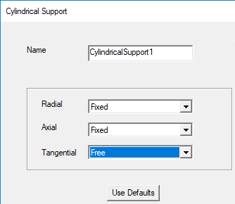
- In the Cylindrical Support dialog box that appears, make the following changes:
- Optionally, change the Name of the boundary. (The default name is CylindricalSupportx, where x is a number incremented for each fixed support you add.)
- Using the drop-down menus, selected the desired state (Fixed or Free) for each of the following directions:
- Radial
- Axial
- Tangential
- Click OK.
- Optionally, if you want to save your cylindrical support settings as the default for future cylindrical supports, do the following:
- Under Boundary in the Project Manager, right-click CylindricalSupportx and choose Properties from the shortcut menu.
- Select the Defaults tab.
- Click Save Defaults:
- On the Desktop ribbon tab, click
 General Options.
 - From the menu bar, click Tools > Options > General Options.
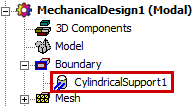
The cylindrical support appears under Boundary in the Project Manager:
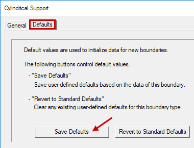
Alternatively, you can click Revert to Standard Defaults to clear any user-defined preferences and restore the original defaults.
Normally, the Defaults tab will not appear when you first assign a cylindrical support boundary. By default, it only appears when you revisit the properties of a previously defined boundary. This behavior is controlled by the option, Use Wizards for data input when creating new boundaries, found under the Mechanical > Boundary Assignment group of settings in the Options dialog box. This option is selected by default. When cleared, all tabs of multi-tab boundary dialog boxes appear immediately when you create a new boundary.
To access the Options dialog box, do one of the following: