Using the Initial Mechanical Transient Setup by RMxprt
To use this method, you need to check Consider Mechanical Transient in the Mechanical tab of the Motion Setup dialog box immediately after the design is created from RMxprt. An example showing the initial values for mechanical transient setup is shown below.
![]()
Note that if you close the design without checking it, and open the design later, this initial mechanical transient setup will loss.
The method for using the mechanical transient setup is as follows:
In the Mechanical tab of the Motion Setup panel, when Consider Mechanical Transient is checked, the displayed Load Torque is actually the "Driving Torque" because the positive torque is defined in the positive speed direction. Therefore, the real positive Load Torque must be defined with a negative value. In order to automatically adjust the speed for the motor to generate the specified output power, you need to set the load torque curve with Constant Power, that is:
Tload = – Pspec / speed
where speed is the real rotor speed, and Pspec is a constant value.
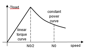
In order to apply this load torque curve for any initial speed, the load torque curve is defined as:
Tload = if(speed<N0/2, -4*Pspec/N0/N0*speed, -Pspec/speed)
where N0 is the synchronous speed for synchronous motors, or the rated speed for other motor types in (rad/s).
The load torque is shown below, which is applicable for all motor types excluding synchronous motors.
For synchronous motors, the motor driving torque varies with torque angle which is the difference between the phase angles of the applied and the induced voltages. If the initial speed is set as the synchronous speed, and the initial torque angle is set smaller than the real value, the motor driving torque will be smaller than the specified load torque. With mechanical transient, the speed will decrease, which makes the torque angle and driving torque increase. When the driving torque equals the load torque, the speed, which is lower than the synchronous speed, will stay constant temporarily. Since the speed is lower than the synchronous speed, the torque angle continues to increase, which makes the driving torque greater than the load torque, and therefore the speed increases. When the speed reaches the synchronous speed, the torque angle will be too large, which will increase the speed to exceed the synchronous speed. Therefore, the speed will oscillate about the synchronous speed. This oscillation will decay to zero if the synchronous motor has a damper cage winding. The decaying time depends on the strength of the damping effects.
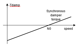
In order to speed up the decaying process, an additional load torque component to model the damping effects around the synchronous speed is set for all types of synchronous motors, as expressed below:
Tdamp = - Tst * (speed/N0 - 1)
where Tst is set as the rated torque. You may increase Tst to increase the damping effects. The damping torque curve is shown below.