
Using Eddy Current Excitation to Generate Harmonic Losses
The 2D Eddy Current and 3D Eddy Current T-W solvers can be used to get harmonic losses on nonlinear systems and can be an alternative to a transient simulation. The Eddy Current Excitations\Winding and Current windows have a Get datasets from FFT option that can be used to reconstruct the signal vs time using a certain amount of harmonics from an FFT plot.
To generate the harmonic losses:
-
For each signal, input the broadband spectrum as datasets of amplitude (A) vs. frequency, phase (f) vs. frequency. While each dataset might have different amplitudes, signals must have the same frequency points.
Note: To use transient data as an Eddy Current excitation, you have the following options:- Get transient data from a third-party simulation (or from a Maxwell transient simulation) and perform FFT outside of Ansys Electronics Desktop to obtain two datasets as Amplitude vs Frequency and Phase vs Frequency. These two can be imported into Ansys Electronic Desktop as datasets and used as arguments within the pwl function of the excitation definition.
- Get transient data from a third-party simulation (or from a Maxwell transient simulation) and import them as datasets and perform the built-in FFT function within excitation window. This action will automatically generate a pwl function with corresponding arguments.
- Define new frequency-dependent datasets within the excitation window by manually introducing the corresponding data pairs, Amplitude vs Frequency and Phase vs Frequency and manually defining the pwl function within corresponding excitation field definition.
-
Solve the frequency sweep and get EM losses on the broadband frequencies.
-
Perform IFFT to get the reconstructed transient signals.
To use existing transient signals, they have to be defined in datasets with the format of signal values versus time.
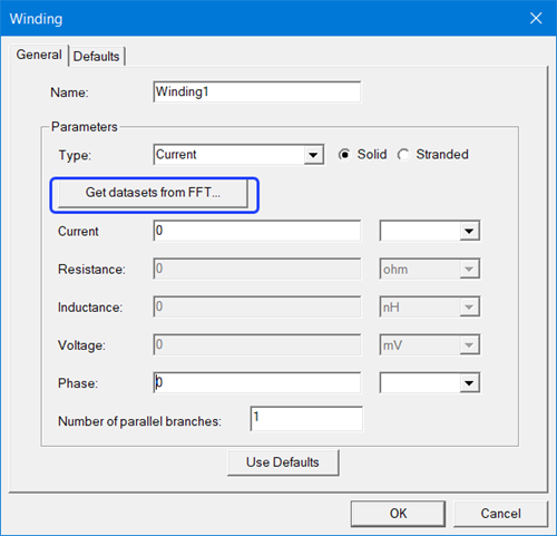
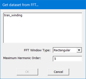
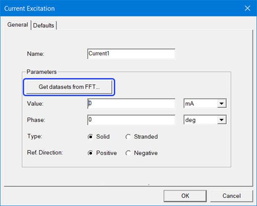
To retrieve the datasets, click the Get dataset from FFT button in the Windings or Current excitations window. In the dialog box that opens, select the desired data set, the FFT Window Type and the Maximum Harmonic Order. Note that the default value for Maximum Harmonic Order is 5. Click OK.
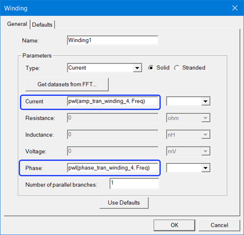
After clicking the OK button, the follow operations occur:
- Two datasets (A, f) and (f , f) are generated and included in the list of design datasets (accessed from Maxwell > Design Datasets). Note that after the datasets are generated, users can modify them.
- Winding values (current/voltage, phase) will be updated with the PWL of these datasets.
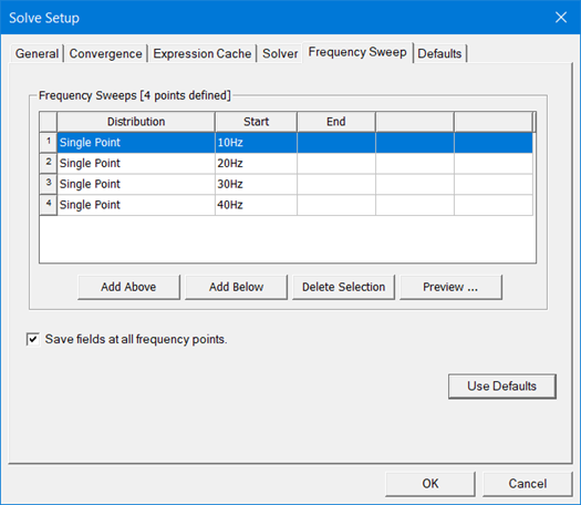
- Frequencies from the FFT process will be added to Solve Setup frequency sweep.
Similarly, for current, the window will also have the button to get datasets from FFT:
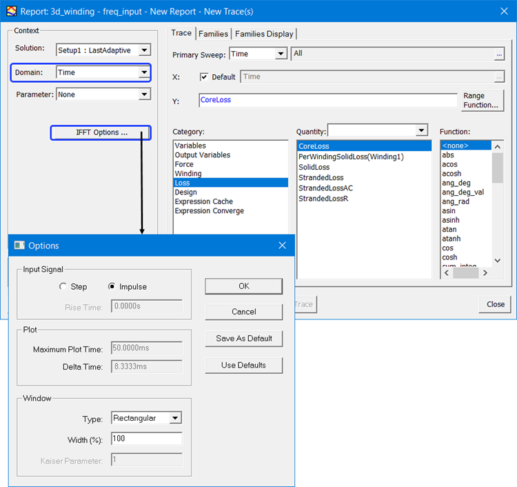
After the Eddy Current simulation is complete, users can use the IFFT function in the Report window to reconstruct the signals. Note that the Domain needs to be Time. Users can also specify the parameters of the IFFT from the IFFT Options window.
Validation
For each signal, the frequency points of (A, f) and (f , f) datasets should be the same.
For all signals, the frequency points of all datasets should be the same.