
User Control Fields Extraction Format
The user.ctl file is created by the user control program. Depending on the solver the following field types are available during export:
| Field | 2D | 3D | 3D A-Phi |
|---|---|---|---|
| B – Magnetic Flux Density | X | X | X |
| H – Magnetic Field Strength | X | X | X |
| J – Current Density | X | X | X |
| A – Magnetic Vector Potential | X | X | |
| Phi - Electric Scalar Potential | X |
To extract fields from Maxwell, the control program must create a user.ctl file with one of the two following syntax strings:
Extract fields on all objects
user.ctl
begin_data
exportFieldAtMeshNodeOnAllObjects
end_data
Extract fields by object ID
user.ctl
begin_data
exportFieldAtMeshNodeOnObject <objectID>
exportFieldAtMeshNodeOnObject <objectID>
end_data
You can get the desired object IDs as follows:
-
Select Tools > Open Command Window.
-
In the following example code snippet, replace "Stator" in the
object_namewith the name of the desired object.object_name = "Stator"
oProject = oDesktop.GetActiveProject()
oDesign = oProject.GetActiveDesign()
oEditor = oDesign.SetActiveEditor("3D Modeler")
object_id = oEditor.GetObjectIDByName(object_name)
print(object_id)
AddInfoMessage(str(object_id)) -
Copy and paste the code snippet into the Command Window and execute.
-
Repeat as needed for additional objects.
Data Structure and Nodes Order for 2D Fields Extraction
|
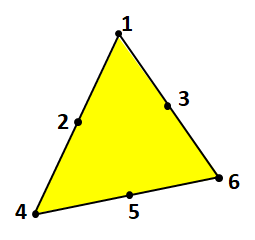
| Node order in Maxwell 2D element |
The Maxwell 2D solver writes the data and updates field files (afield.ctl, bfield.ctl, hfield.ctl, jfield.ctl) at each time step with the following structure:
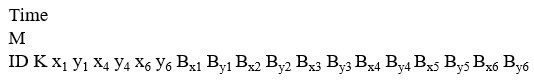
where:
- Time – is the time corresponding to the time-stepping FE solution
- M – is the total number of elements
- ID – is the object ID
- K – is the element number
- xi, yi – are the coordinates of node i, for i in [1, 4, 6]
- Bxi Byi – is the field X, Y component value of node i, for i in range 1 to 6
The following is an example for bfield.ctl data extracted in an object with ID 761 that consists of 2 elements at t = 0.04 sec.

Data Structure and Nodes Order for 3D Fields Extraction
|
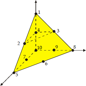
| Node order in Maxwell 3D element |
The Maxwell 3D solver writes the data and updates field files (bfield.ctl, hfield.ctl, jfield.ctl) at each time step with the following structure:
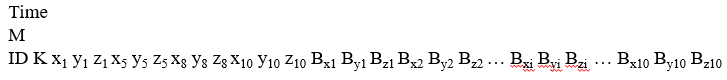
where:
- Time – is the time corresponding to the time-stepping FE solution
- M – is the total number of elements
- ID – is the object ID
- K – is the element number
- xi, yi, and zi– are the coordinates of node i, for i in [1, 5, 8, 10]
- Bxi Byi, Bzi – is the field X, Y, Z component value of node i, for i in range 1 to 10
Related Topics
Using a Control Program in Maxwell 2D and 3D Transient Solutions