
Types of Inductance
For nonlinear materials, the definition of inductance requires additional detail compared to the linear case. Three commonly used inductance values are illustrated in the figure above - each inductance has useful applications. Maxwell uses apparent inductance to calculate flux linkage as a function of the independent variables, since it changes with current as the material properties change. To obtain apparent inductances for nonlinear materials in Maxwell, a two-step procedure is followed:
- A nonlinear magnetostatic solution is generated with all sources at user specified values. This establishes a value of permeability that varies with each mesh element, since the degree of saturation varies throughout the device.
- These self-consistent values are used in a linear solution for the inductance matrix, with each coil current set to one ampere. The resulting values are apparent inductances, which vary with each specified coil current operating point because the material properties change.
The inductance calculation is now linearized on the self-consistent values. If the coil currents had been increased to the specified values in the first step, in the linearized model, the resulting magnetic field would be identical to the nonlinear solution. Therefore, the inductances from the second step are the ratios of respective flux linkages to coil current, at the nonlinear operating point originally determined.
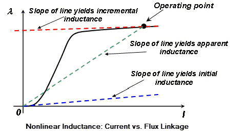
The slope of any line drawn on the figure above has units of inductance (henries) and any area enclosed on this plot represents units of energy in joules if magnetic flux is expressed in Webers and current is expressed in Amperes. The three inductances are defined as:
|
Incremental(differential) inductance
|
The slope of a line tangent to the curve at the operating point. Incremental inductance is the usual textbook definition. For small signal AC analysis in Maxwell SPICE or Saber, incremental inductance is evaluated using an operating point determined from a DC solution. Incremental inductance can also be used in time domain system simulations by using the compensation theorem, but it has no useful relationship to stored energy. |
|
Apparent inductance
|
The slope of a line from the origin to the operating point. Apparent inductance gives the total flux linkage as a function of current, so it is well-suited for the state equation or basis function approach to time domain simulations. For small-signal AC analysis, apparent inductance cannot be used directly, but can be used to supply the proper derivatives to Maxwell SPICE. Energy can be calculated with apparent inductance, but the result is not really the stored energy because it ignores the path taken along the nonlinear curve. Apparent inductance does not provide the actual stored energy at the specified operating point. However, during time domain simulations, apparent inductance varies with current, and tracks the nonlinear curve shown in the figure. |
|
Initial inductance
|
The slope of a line tangent to the curve at the origin. Initial inductance applies to many magnetic materials that have a "toe" in the magnetization curve. Laboratory measurements at 0 A DC measure initial inductance, not the "linear" value that may be somewhat higher. Note: Initial inductance is a particular case of the incremental inductance where the slope of the respective line passes through the origin of the (flux - current) plane. |


For linear materials, all three inductance values are equal. For nonlinear materials, the three values are generally different. Except for initial inductance, each value varies with the operating point. Ignoring the "toe" of the curve, the relation Lapp > Linc holds. Energy taken from or supplied to the external circuit, as determined from the terminal voltage and current, will be correct.
The apparent inductance calculated by Maxwell at the actual operating point due to all sources in the model (currents in the coils but also permanent magnets) is the base of all inductance calculations. Incremental (differential) inductance information can be easily derived from the flux vs current characteristic.
It should be noted that the apparent value relates to the local frozen, current dependent absolute permeability as described above in the two step process. Incremental inductance relates to another physical quantity which is the differential (incremental) permeability defined as dB/dH.
Solver calculated magnetostatic energy (reported as part of the solution convergence data) is the apparent energy, always equal to the global, model-wise average between energy and co-energy. For the linear material case in the entire model there is only one value of the inductance L = Linit = Lincr = Lapp.