
Example: Using System Coupling for Electrical Arc Modeling
To model an electrical arc, System Coupling can be used with Maxwell and Fluent, as well as with Twin Builder. All participants in the System Coupling are coupled and dependent on each other. The workflow for this type of modeling has the following order: Twin Builder > Maxwell > Fluent. Multiple iterations (data exchanges) can occur between each two participants.
As seen in the flow chart, Maxwell provides voltage to an external circuit in Twin Builder (through a FMU model), and then Twin Builder feeds a current to Maxwell through a circuit model. Then Maxwell generates volume loss, surface loss (including nonlinear resistance thin layer losses on Electric Arc Anode and Cathode surfaces) and Lorentz forces for Fluent. Fluent can consume heat rate (surface loss from Maxwell) on solid-fluid interfaces, and it feeds electrical conductivity and temperature back to Maxwell.

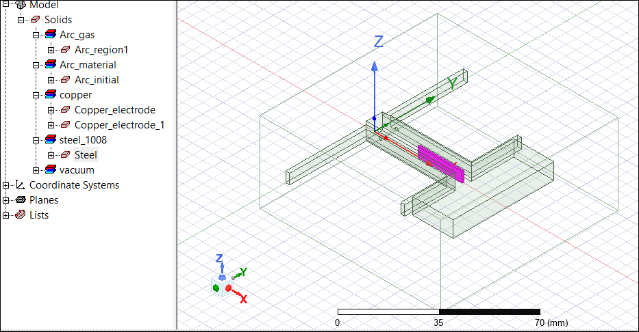
The model used for this example is an electric arc between two run rails. The Maxwell model is shown below:
This example assumes that the user is familiar with the Twin Builder, Maxwell, and Fluent tools, so it will only detail the requirements for the System Coupling setup. For details on the individual tools, see the corresponding reference and tutorial topics.
Maxwell Setup
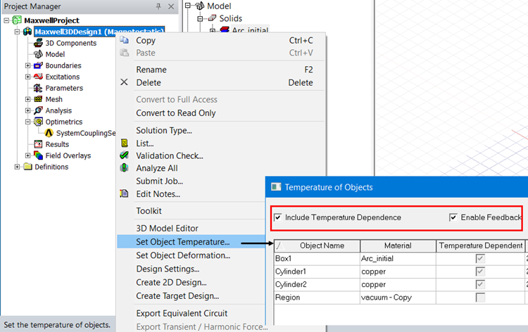
For the Maxwell model, the arc material should have the Thermal Modifier and Spatial Modifier options checked for Bulk Conductivity, and the Spatial Modifier should be set to 1.

For the model Temperature of Objects, check Include Temperature Dependence and Enable Feedback:
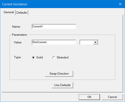
Set up the desired magnetostatic simulation, including boundaries, current excitations, and simulation time:
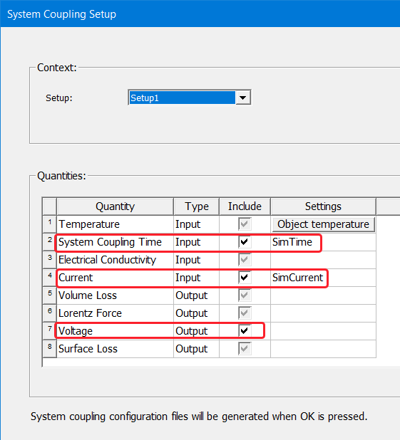
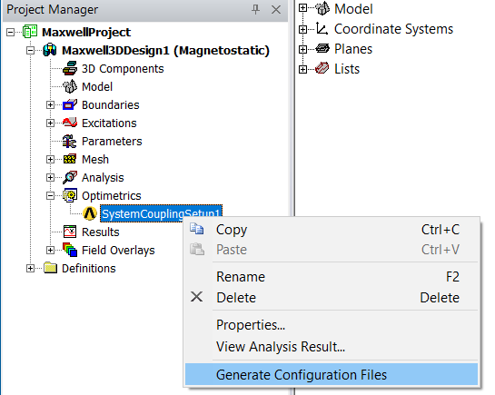
Add a System Coupling Setup to the Optimetrics folder, and set the following:
-
Check System Coupling Time, and set the Settings variable to SimTime.
-
Check Current, and set the Settings variable to SimCurrent.
-
Check Voltage.
After finishing the Maxwell setup, generate the configuration files needed for System Coupling:
Fluent Setup
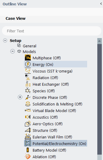
For the Fluent model, the materials should have the same properties as the Maxwell model. The Energy and the Potential/Electrochemistry models should be turned on. Potential is needed because it is used to calculate the Electrical Conductivity required by Maxwell.
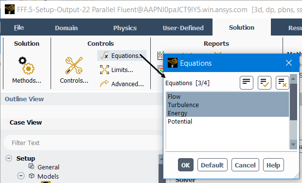
From the Solution panel, the Potential equation must be deactivated because electromagnetics will be simulated in Maxwell:
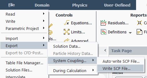
After setting any required properties and boundary conditions for your model, export the Fluent setup to a System Coupling file:
System Coupling Setup
Load the System Coupling participants one by one following the order Twin Builder FMU Model > Ansys Electronics Desktop Maxwell > Fluid Flow: click Add Participant icon ![]() , and in the dialog box that opens, find the input files for each participants and add one by one.
, and in the dialog box that opens, find the input files for each participants and add one by one.
- The input file for TwinBuilder is a .fmu file.
- The input file for AEDT is a \\MaxwellProject_Maxwell3DDesign_SystemCouplingSetup1.scp file.
- The input file for Fluid Flow is a \\Fluent\fluent.scp file.
Note that the order in which they were added reflects the order in which they have to be solved.
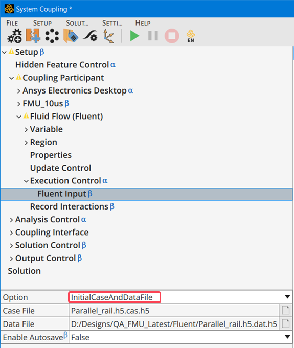
For the Fluid Flow\Fluent Input, add the Fluent case and data files in from the \\Fluent directory:
Add three Coupling Interfaces: One between the FMU model and Maxwell and two between Maxwell and Fluent. For Maxwell\Fluent interfaces, select a region or regions for each side where the data will be exchanged: for CouplingInterface2/Side 2, the region specified for Fluent is a fluid; for CouplingInterface3/Side 2, the regions specified for Fluent are the solid-fluid interfaces.
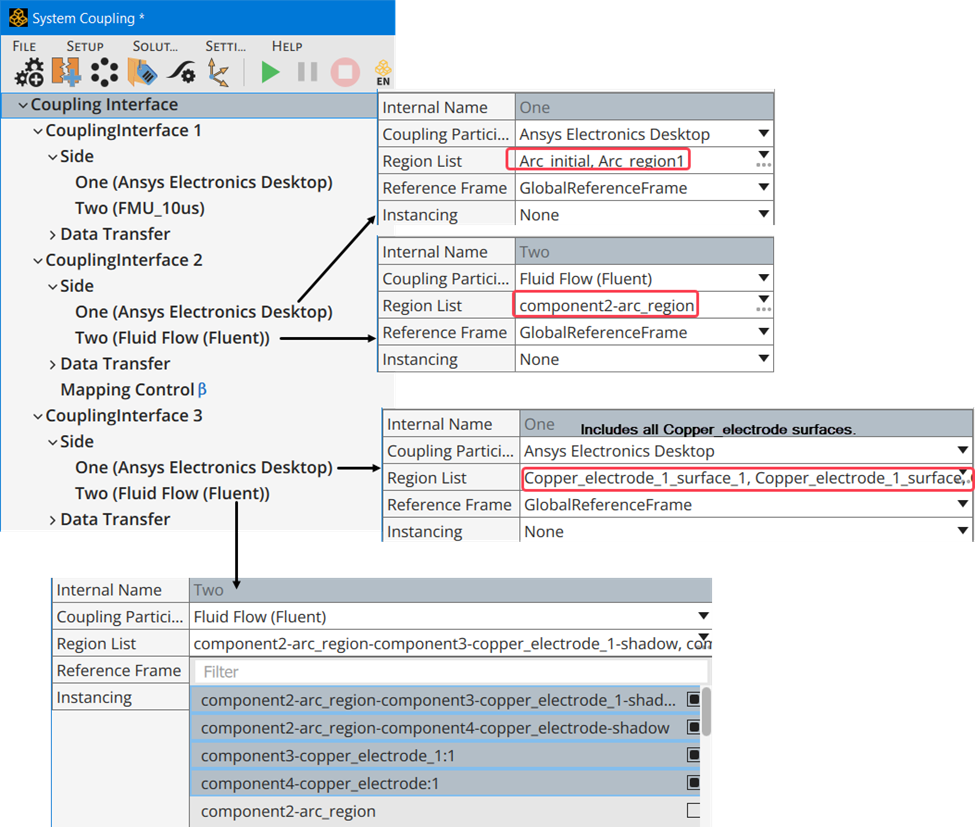
For each coupling interface, specify the data that will be transferred. The example setup includes the following:
- CouplingInterface1\DataTransfer 1: i_out is transferred to Side 1(Maxwell) as Current.
- CouplingInterface1\DataTransfer 2: Voltage is transferred to Side 2 (Twin Builder model) as voltage in.
- CouplingInterface2\DataTransfer 1: Electrical Conductivity is transferred to Side 1 (Maxwell) as conductivity.
- CouplingInterface2\DataTransfer 2: LorentzForce is transferred to Side 2 (Fluent) as Lorentz_Force
- CouplingInterface2\DataTransfer 3: Loss is transferred to Side 2 (Fluent) as heatrate.
- CouplingInterface2\DataTransfer 4: temperature is transferred to Side 1 (Maxwell) as Temperature.
- CouplingInterface3\DataTransfer 1: SurfaceLoss is transferred to Side 2 (Fluent) as heatrate.
![]()
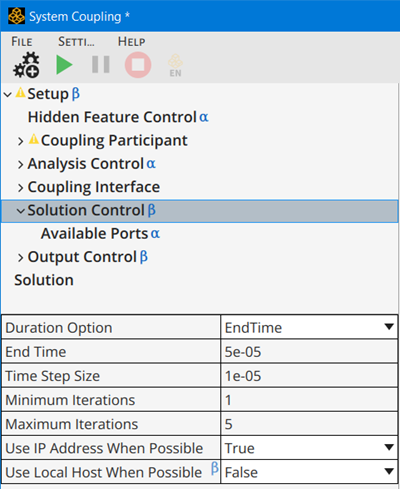
When the System Coupling is executed, it will run according to the end time, timestep and iterations specified in the Solution Control setup:
When the system coupling is executed, Maxwell will output the arc voltage (calculated through loss/current) to the external circuit arc voltage interaction with network, and Maxwell will input the arc current from the external circuit (Twin Builder FMU). Maxwell loss and surface loss calculations will be output to Fluent, which will input conductivity and temperature into Maxwell.
The simulation can be monitored from the Command Console tab, and plotted results will be available from the Chart tab when the simulation is finished.

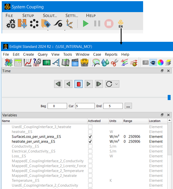
To see how well data is transferred from one region to another, we can use Ensight to compare Maxwell surface loss to Fluent heat rate:
To visualize surface loss in Maxwell, right-click on the surface in the Modeler window, and select Fields > Other > Surface Loss Density.

Related Topics
Coupling Maxwell Magnetostatic and Eddy Current Designs with Ansys Fluent