SynRMCore UDP
The SynRMCore UDP is used to create the rotor core for synchronous reluctance machines.
|
Property |
Description |
|
DiaGap |
Core diameter on gap side, or outer diameter |
|
DiaYoke |
Core diameter on yoke side, or inner diameter |
|
Length |
Core length |
|
Poles |
Number of poles |
|
PoleType |
1: ALA; 2: arc; 3: hyperbolic; 4: hyperbolic line |
|
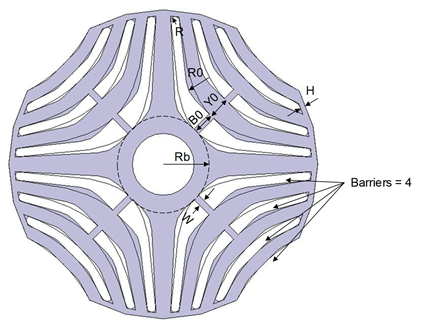
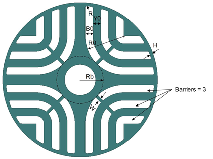
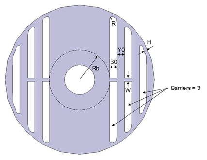
Barriers |
Barriers per Pole, for PoleType 2 & 3 only |
|
H |
Bridge thickness, for PoleType 2 & 3 only |
|
W |
Rib width, for PoleType 2 & 3 only |
|
R |
Barrier fillet radius, for PoleType 2 & 3 only |
|
R0 |
Radius of the bottom barrier arch, for PoleType 2 only |
|
Rb |
Barrier bottom minimum radius |
|
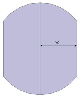
Y0 |
Yoke bottom thickness |
|
B0 |
Barrier bottom thickness, for PoleType of 2 & 3 only |
|
LenRegion |
Region length |
|
InfoCore |
0: core; 1: one barrier; 100: region |
The SynRM UDP supports four pole types:
- Type 1 – axially laminated core
- Type 2 – barriers with concentric arcs and lines
- Type 3 – barriers with hyperbolic curves
- Type 4 – barriers with hyperbolic polylines

Type 1 |

Type 2 |

Type 3 |

Type 4 |
Parameters for SynRM core with PoleType = 1
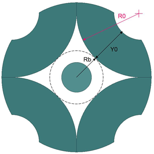
In the figure, R0 is a derived parameter, as given below:
R0 = Rbsin θ/(1 − sin θ)
where θ = π/p, and p, the number of poles, should be ≥ 4.
The center point (x, y) of the R0 circle is:
x = (Rb + R0)cos θ
y = (Rb + R0)sin θ
Below is a two-pole SynRM core with PoleType = 1.
Parameters for SynRM core with PoleType = 2
Below is a two-pole SynRM core with PoleType = 2
Parameters for SynRM core with PoleType = 3
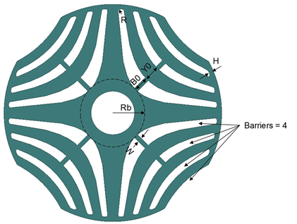
The main edges of barriers for Type 3 are hyperbolic curves defined by
r2 sin(pp • θ) = Rm2
x = r • cos θ
y = r • sin θ
where pp is the number of pole pairs, π/pp > θ > 0, and Rm is the minimum radius of a hyperbolic line. For different Rm values, you will get different hyperbolic curves.
The first barrier is created based on the following two hyperbolic curves:
- for the bottom hyperbolic curve, Rm2 = Rb
- for the top hyperbolic curve, Rm1 = Rb +B0
The second and all other barriers are created based on a constant minimum barrier width and minimum tooth width at maximum limit radius which is derived from outer radius minus the value of bridge thickness parameter H.
The minimum barrier width and minimum tooth width can be derived from B0 and Y0, respectively. If the top and bottom hyperbolic curves are defined by Rm1 and Rm2, respectively, and let r to be the maximum limit radius, you can obtain two points (x1, y1) and (x2, y2) at the maximum limit circle intersected with the top and bottom hyperbolic curves, respectively, based on the above hyperbolic curve equation. Note that the distance between these two intersection points is not the minimum width because the connection line is not perpendicular to the center hyperbolic curve. The angle between the connection line and normal line is the angle between the r line and the tangent line which can be computed from dy/dx and θ of the center hyperbolic curve at the maximum limit radius.
Parameters for SynRM core with PoleType = 4
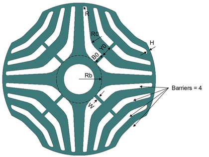
The main edges of barriers for Type 4 are hyperbolic polylines. A hyperbolic polyline is derived from a hyperbolic curve. It consists of one bottom line (tangent to the bottom points of the hyperbolic curve), two side lines (tangent to the point on the hyperbolic curve at the maximum limit radius), and fillet arcs defined R0. The value of fillet radius R0 is the same for all hyperbolic polylines. All parameters for hyperbolic curves to derive hyperbolic polylines are defined in the same way as those for pole Type 3. The following figure shows how barriers of Type 4 are derived from those of Type 3.